
Masonry Wall: Types, Parts and How to Specify One
Identify masonry wall types, distinguish nominal and actual sizes, and coordinate structure, drainage, movement joints, ties and reinforcement.
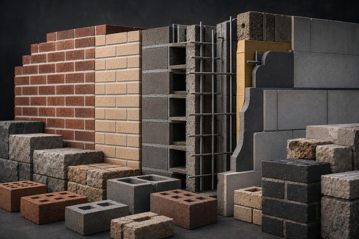
A masonry wall is an assembly of brick, concrete masonry units (CMU), stone or other masonry units, usually arranged in courses and joined with mortar or another approved system. Grout, reinforcement, ties, anchors, cavities, flashing and sealant may perform separate structural or weather-control functions.
The visible material does not reveal whether the wall carries the building. A brick face may be nonstructural veneer tied to CMU, wood or steel-stud backing, while an exposed CMU wall may itself be structural.
Masonry wall types at a glance
| Wall type | Basic arrangement | Structural action | Main detailing issue |
|---|---|---|---|
| Single-wythe wall | One continuous masonry section one unit thick, often CMU | The masonry may carry gravity and lateral loads or serve as a nonbearing partition | Reinforcement, crack control and moisture resistance without a continuous cavity |
| Multi-wythe composite wall | Two or more masonry wythes connected to act together | The combined section resists the applied loads | Connections that develop composite action |
| Multi-wythe noncomposite wall | Two or more connected wythes designed to resist load separately | Each wythe resists its share according to its relative stiffness | Correct ties and allowance for differential movement |
| Anchored masonry veneer | Exterior masonry wythe, cavity and mechanically anchored backing | The veneer supports its self-weight and transfers out-of-plane loads through anchors; the backing carries the building loads | Support, ties, cavity drainage, flashing and movement joints |
| Adhered masonry veneer | Thin masonry units bonded to an approved backing | The veneer transfers its weight and out-of-plane loads through the bonding system to the backing | Approved substrate and bonding system, water management and terminations |
The 2024 International Building Code defines anchored masonry veneer as veneer secured by approved mechanical fasteners and adhered masonry veneer as veneer secured and supported by an approved bonding material. Chapter 21 directs masonry veneer to Chapter 14, while establishing the broader requirements and referenced standards for masonry construction (ICC, 2024 IBC definitions; ICC, Chapter 21).
For multi-wythe construction, the structural distinction is not semantic. CMHA describes a true veneer as nonstructural, a noncomposite wall as wythes resisting their shares of load individually, and a composite wall as wythes acting together as one member (CMHA, TEK 05-01B).
Read the wall as units, joints and wythes
A course is a continuous horizontal layer of units. A wythe is a continuous vertical section one masonry unit thick. The bed joint is the horizontal mortar layer beneath a unit; the head joint is the vertical mortar joint between units. Bond can describe the geometric pattern, the connection between parts of a wall or adhesion between masonry materials (BIA, Technical Note 2).
That vocabulary prevents common mistakes. Running bond and stack bond describe unit layout, not whether the wall is loadbearing. Likewise, one visible brick wythe does not prove that a wall is solid brick: the backing and connections may be concealed. See brick wythe terminology, solid brick wall identification and the distinction between pattern and structure in brick bonds.
Keep nominal, specified and actual dimensions separate
Modular masonry is laid out using a unit-plus-joint module, not the unit dimensions alone.
For a common US precision CMU:
| Dimension being discussed | 8 × 8 × 16 CMU example |
|---|---|
| Nominal unit size | 8 × 8 × 16 in. |
| Specified unit size | 7⅝ × 7⅝ × 15⅝ in. |
| Intended mortar joint | ⅜ in. |
| Installed module | 8 in. high × 16 in. long |
Nominal dimensions state the modular size. Specified dimensions are the manufacturing target used for design. Actual dimensions are measurements of the manufactured unit and may vary within the applicable tolerance. The width-height-length order also matters. Manufacturer data for standard precision CMU lists the dimensions above and explains that nominal size equals specified size plus the intended joint (Angelus Block). For unit selection beyond this example, see concrete masonry unit sizes and documentation.
Brick uses the same distinction when it is modular, but not every brick is modular. BIA advises specifying brick by width × height × length because regional and manufacturer size names can differ. Its modular-brick tables combine specified unit dimensions with intended joints to establish nominal modules; nonmodular brick has specified and actual dimensions but no nominal dimensions (BIA, Technical Note 10).
Before specifying a wall, answer six questions
- Which units? State the material, applicable standard, manufacturer or acceptable products, specified dimensions, finish, color and special shapes. ASTM C90 is the commonly encountered US specification for loadbearing dry-cast CMU, but the code-adopted and project-specified edition matters (CMHA, CMU-TEC-001).
- Which mortar and joints? State the mortar requirements, joint thickness and joint profile. Mortar is not interchangeable with neat cement; use the specified masonry mortar system. Compare masonry mortar types.
- What is the structural role? Identify bearing or nonbearing construction, reinforcement, grout, anchors, ties, lintels, bond beams and connections to floors or roofs. A CMU bond beam is a reinforced, grouted wall course—not simply any special-shaped block.
- How does water leave? For drained veneer, coordinate the cavity, flashing, weeps and drainage material. For anchored brick veneer over CMU, BIA recommends a 2 in. (51 mm) air space and identifies 1 in. (25.4 mm) as the minimum under the stated conditions. It recommends flashing where the air space is interrupted and weeps immediately above the flashing (BIA, Technical Note 28D). Mortar droppings can obstruct the drainage path, so cavity cleanliness and collection devices must be coordinated with the specified clearance.
- How can materials move? Locate control joints for concrete masonry and expansion joints for clay brick, coordinating them with openings, supports, sealants and the backing. Ties must transfer the required lateral loads while accommodating the movement assumed by the design.
- How are edges and openings resolved? Show foundation transitions, heads, sills, jambs, shelf angles, parapets, copings and penetrations. Flashing must drain to the exterior rather than merely exist inside the wall. For roof-edge construction, read the masonry parapet detail as a complete assembly.
The project documents must also establish applicable performance requirements, such as fire resistance, thermal and moisture control, exposure and acoustic performance. These are properties of the complete assembly, not of the visible unit alone.
Single-wythe CMU deserves particular attention because it has no continuous drainage cavity. CMHA recommends redundant moisture protection using surface protection, internal protection, and drainage or drying. Cracks, penetrations and interfaces remain potential water-entry points even when water repellents are used (CMHA, TEK 19-02B).
Do not select a masonry wall from appearance or nominal thickness alone. Confirm the wall section, structural drawings, unit data, mortar, reinforcement, movement joints and water-management details as one coordinated system.