
Parapet Detail: How a Masonry Roof Edge Fits Together
Read a masonry parapet detail layer by layer, from coping and through-wall flashing to roof membrane, insulation, movement joints and structure.
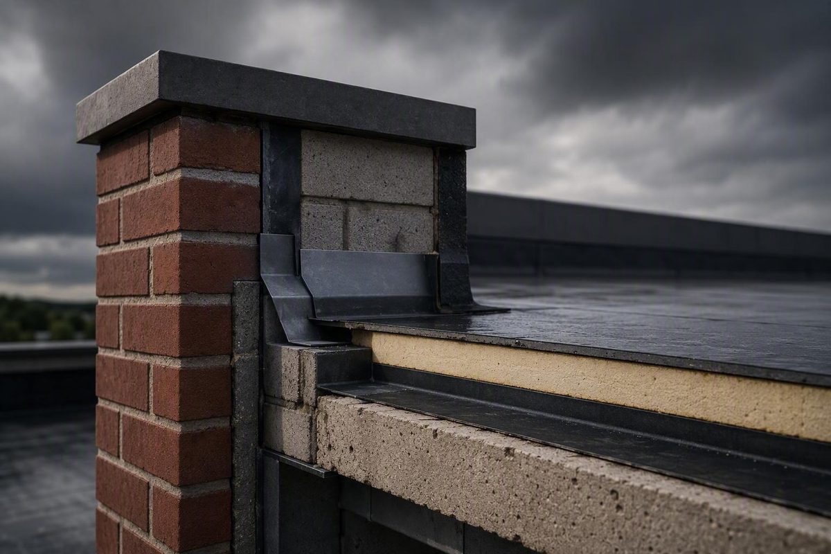
A masonry parapet detail must coordinate the coping, concealed flashing, masonry wythes, roof membrane, insulation and air barrier, and structural support. It is not enough to draw a cap over a wall and turn the roofing upward.
The detail should show a continuous route for water back to the roof or out through flashing, while allowing the roof, coping and masonry to move without tearing membranes or restraining joints. For terminology and common parapet forms, see Parapet: Meaning, Types, Uses & Details.
Read the section from the top down
| Zone | What the detail should show | What to verify |
|---|---|---|
| Coping | Metal, stone, precast concrete or masonry covering; slope; joints; cleats or anchors | Positive slope, drips, securement and movement accommodation |
| Under-coping protection | Continuous waterproof membrane or through-wall flashing | Laps, sealed penetrations, end conditions and connection to wall water control |
| Masonry | Brick veneer, CMU backup or single-wythe construction | Unit geometry, full joints where specified, reinforcement, grout and movement joints |
| Roof-to-wall transition | Roof membrane rising at the parapet, with termination and counterflashing where required | Compatible materials, manufacturer-approved termination and allowance for differential movement |
| Enclosure layers | Wall water-resistive barrier, air barrier, insulation and any required vapor control | Each layer can be traced continuously from wall to roof |
| Structure | Parapet reinforcement, anchors, roof-edge blocking and deck connection | Design for wind and other project loads; attachment does not compromise flashing |
1. Coping sheds water; flashing provides the backup
The coping is the exposed top covering, not the complete waterproofing strategy. The Brick Industry Association (BIA) states that copings should overhang both faces and that the inner lip of a drip should be at least 1 in. (25 mm) from the wall face. Its guidance also calls for a drip regardless of coping material (BIA Technical Note 36A).
Slope the coping toward the roof where the assembly permits, rather than directing runoff over the façade. Put a continuous waterproof membrane beneath it because metal and stone coping joints are not assumed watertight; provide drips at both edges (Building Science Corporation).
A stone or precast coping detail should identify bed joints, sealant joints, anchors and flashing penetrations. A metal coping detail should identify cleats, splice or joint treatment, corner pieces and attachment. CMHA guidance for concrete masonry calls for metal caps to extend at least 4 in. (102 mm) over the masonry face and be sealed on both sides (CMHA TEK 19-05A). These are component dimensions, not substitutes for project-specific wind design.
2. Keep roof and wall water control connected—but not accidentally bonded together
At the roof side, show where the roof membrane rises, how it is supported and where it terminates. Do not leave “roofing up wall” as an unresolved note. CMHA warns that joining materials with substantially different thermal expansion can tear the joint, and that some roof membranes may shrink with age; its illustrated approach uses counterflashing so the roof termination remains accessible during reroofing (CMHA TEK 19-05A).
The exact termination depends on the roof system. It may involve a termination bar and counterflashing below the coping, or a manufacturer-approved membrane arrangement carried higher. Show transitions, laps, corner pieces and sealant as buildable components rather than relying on a single line in section.
On the exterior side, lap the under-coping membrane over the wall’s secondary water-management layer in shingle fashion and seal coping-fastener penetrations. At the same time, let the roof membrane accommodate differential movement where it meets the parapet (GAF).
3. Trace all four enclosure layers
A useful review method is to trace four separate lines through the detail:
- Water control: roof membrane to wall flashing or water-resistive barrier, with under-coping protection above.
- Air control: roof air-control layer connected and sealed to the wall air barrier.
- Thermal control: roof insulation connected to wall insulation without an unaddressed gap at the deck edge or parapet.
- Vapor control: included only where the climate, occupancy and roof/wall assemblies require it, then connected consistently.
Building Science Corporation summarizes the principle as continuity of the water, air, vapor and thermal control layers between roof and wall (BSI-050). A detail that solves only the visible coping can still leave a concealed air leak, thermal bridge or condensation surface.
4. Continue movement joints through the top
Do not stop a masonry movement joint below the parapet or bridge it with rigid coping. Brick uses expansion joints; concrete masonry commonly uses control joints. They serve different movement mechanisms and are not interchangeable.
For brick veneer, BIA says vertical expansion joints should extend to the top of the brickwork, including parapets. It also advises wider or additional parapet joints when spacing between vertical expansion joints exceeds 15 ft (4.6 m) (BIA Technical Note 18A). The coping joint should align with the wall joint where required, while metal coping is detailed to move independently rather than locking adjacent masonry segments together.
At a low parapet intersecting a higher wall, a normal two-dimensional section is insufficient. The detail needs a saddle or end condition showing membranes, end dams, counterflashing and the high-wall drainage path. IMI’s anchored-brick example uses a sealed or soldered one-piece saddle flashing, a receiver with an end dam and a vertical expansion joint at the change in bearing condition (International Masonry Institute).
Parapet-detail review checklist
Before issuing the detail, confirm that it identifies:
- coping material, slope, drips, joints, cleats or anchors;
- a continuous under-coping membrane, including sealed penetrations;
- roof-membrane support, termination and counterflashing;
- wall flashing or water-resistive-barrier laps;
- air-barrier and insulation continuity at the roof edge;
- brick expansion joints or CMU control joints, correctly named and coordinated;
- reinforcement, grout, anchors and structural attachment;
- inside and outside corners, ends, steps and high-wall intersections;
- compatible metals, membranes, sealants and treated-wood components; and
- enough dimensions and enlarged views for the trades to build the transitions.
A sound parapet detail therefore works as an assembly drawing: every layer has a route, every joint has room to move, and every termination can be installed and maintained.