
What Is a CMU Lintel Assembly?
It is more than a block: the spanning member, required reinforcement, grout or concrete, bearing zones, jambs, connections and temporary support all matter.
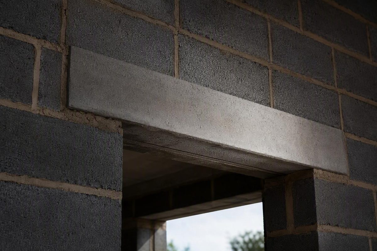
A door or window interrupts a masonry wall, but the loads above it do not disappear. A lintel bridges the opening and redirects those loads into the masonry on each side.
Although “CMU lintel” can sound like the name of a block, the relevant structural unit is the complete assembly: the masonry or prefabricated spanning member, reinforcement where required, grout or concrete, bearing zones, jambs, connections, and temporary support during construction.
That distinction matters because two openings of the same width can impose very different demands. One lintel may support only a modest height of non-load-bearing masonry. Another may receive a floor, roof, beam, joist, ridge, veneer, or concentrated reaction. Dimensions describe part of the problem, but they do not establish structural adequacy.
This article explains terminology, conceptual load paths, selection factors, and document coordination. It does not provide a universal span table, reinforcement schedule, bearing length, shoring plan, or approval for a particular opening. Applicable code editions, local amendments, project documents, and manufacturer requirements must be verified for the jurisdiction and project.
What a CMU lintel does above an opening
A lintel is a horizontal structural member that spans an opening in a concrete masonry wall. It supports the masonry above the opening and any additional loads assigned to it, then transfers the resulting reactions into the wall or jambs at both ends. Depending on regional terminology, “lintel” and “beam” may be used interchangeably even though the materials and construction details vary, as explained in the Concrete Masonry and Hardscapes Association lintel manual.
Typical locations include:
- Door and window heads
- Fireplace openings
- Mechanical, electrical, and plumbing penetrations
- Recesses and pass-through openings
- Vehicle and equipment doors
- Openings between adjoining rooms or process areas
The basic load path can be separated into five steps:
- Masonry and other supported construction create downward loads.
- Those loads reach the lintel above the opening.
- The lintel resists the resulting bending and shear demands.
- The lintel ends deliver reactions into the bearing zones.
- The jamb masonry carries those reactions into the structure below.
A simplified conceptual diagram looks like this:
       Supported masonry and other assigned loads
          ↓       ↓       ↓       ↓       ↓
    ┌─────────────────────────────────────────┐
    │             MASONRY ABOVE               │
    └─────────────────────────────────────────┘
          ↓       ↓       ↓       ↓
    █████████████  LINTEL  █████████████
        ↑                               ↑
     end reaction                    end reaction
        │                               │
   designed bearing                designed bearing
      and jamb                        and jamb
        │                               │
        └──── load continues to supports ────┘
This is not a construction detail. It omits reinforcement, arching, concentrated loads, wall ties, veneer, movement joints, connections, and the distinction between structural and nonstructural masonry. Any of those conditions can change the demand or required detail.
Clear span is therefore only one design input. Other important variables include:
- Height and weight of the supported masonry
- Floor or roof reactions
- Concentrated loads near or above the opening
- Wall thickness and structural role
- Available lintel depth
- Masonry, grout, concrete, and steel properties
- Reinforcement size, quantity, position, and anchorage
- End-bearing length and jamb construction
- Deflection and cracking criteria
- Exposure, fire, moisture, and movement requirements
- Construction sequence and temporary support
A shallow lintel over a wide opening behaves differently from a deeper member over the same opening. Identical lintels can also experience different demands if one receives a roof reaction while the other supports masonry alone. A useful CMU lintel discussion therefore begins with the complete load path, not with a product length.
Lintel block, bond beam, precast lintel, and steel: the terms separated
Products called masonry lintels do not all work in the same way. Four categories should be kept distinct: site-built reinforced masonry lintels, bond beams, precast reinforced-concrete lintels, and steel lintels.
Site-built reinforced masonry lintel. This system commonly uses U-shaped concrete masonry units laid with the channel facing upward. Designed horizontal reinforcing bars are placed in the channel, which is then filled as specified. The completed reinforced course—not the empty row of units—is intended to span the opening.
A typical lintel unit has a solid bottom beneath its channel. The bottom contains the fluid fill during construction, but it prevents a vertical reinforcing bar from passing directly through that portion of the unit. The lintel course must therefore be coordinated with jamb and wall reinforcement.
Bond-beam course. Bond-beam units may have open bottoms, removable webs, or knockout sections. Those configurations can accommodate intersections between horizontal and vertical reinforcement, subject to the designed detail. Because an open-bottom unit can allow grout to descend into lower cells, the assembly may require mesh or another specified grout-flow control.
A bond beam also has broader wall functions. It may provide horizontal continuity, distribute forces, assist with crack control, connect walls to floors or roofs, or form part of the wall’s wind- or seismic-force-resisting system. A properly designed bond beam may act as a lintel, but that does not make every bond-beam unit interchangeable with every solid-bottom lintel unit. The geometric and reinforcement distinctions are illustrated in Nitterhouse Masonry’s comparison of bond-beam and lintel blocks.
Precast reinforced-concrete lintel. A precast lintel is fabricated before delivery rather than assembled from ordinary masonry courses at the opening. It may be a solid reinforced member or a manufacturer-specific U-shaped product with a channel for reinforcement. Capacity, lifting, orientation, bearing, installation, and connection requirements depend on the actual product and project.
Steel lintel. Steel angles, bent plates, channels, and structural beams are separate structural systems, not varieties of CMU block. Depending on their configuration, they may support structural masonry, veneer, or both. Their design must address the actual member, bearing, connections, stability, deflection, exposure, and fire requirements.
The terminology can be summarized conceptually:
SITE-BUILT LINTEL UNIT       BOND-BEAM UNIT
┌───────────────────┐       ┌───────────────────┐
│ fill + horiz. bar │       │ fill + horiz. bar │
│        ●          │       │        ●          │
└───────────────────┘       └───────   ─────────┘
  solid unit bottom            open/knockout bottom
  blocks direct vertical       may accommodate a
  bar passage                   vertical bar
                                      │
                                      ●

PRECAST CONCRETE             STEEL
███████████████████          ───────── angle
fabricated member            ╚════════ bent plate
                             I════════ structural beam
These are terminology sketches, not approved sections. Product geometry varies, and a precast U-shaped lintel should not automatically be treated as equivalent to either a site-built lintel block or a bond-beam unit.
A useful specification identifies the intended system rather than stating only “provide CMU lintel.” It should distinguish among:
- A reinforced and filled masonry lintel course
- A reinforced bond beam designed to span an opening
- A proprietary or standard precast reinforced-concrete member
- A steel angle, plate, channel, or beam
- A coordinated combination of steel and reinforced masonry
That clarity helps prevent purchasing errors and exposes reinforcement or geometry conflicts before construction.
How a site-built reinforced masonry lintel is assembled
A site-built lintel becomes a structural assembly through the combination of units, reinforcement, specified fill, bearing, and surrounding masonry. Empty U-shaped units are not a substitute for the completed reinforced section shown in the project documents.
At a conceptual level, the work ordinarily requires coordination of the following activities:
- Provide the temporary support required by the project’s erection or sequencing plan.
- Place the specified lintel units in their required orientation.
- Install grout stops or other flow controls where the unit geometry requires them.
- Place and secure the designed horizontal reinforcement in its specified position.
- Coordinate the lintel reinforcement with jamb bars, grouted cells, and other wall reinforcement.
- Place the specified grout or concrete using the project-defined placement and consolidation procedures.
- Protect and cure the work as required by the applicable documents.
- Retain temporary support until the documented release criteria have been satisfied.
- Complete required observations, inspections, or documentation before concealing critical work.
This is an explanatory sequence, not an installation specification. Bar sizes, cover, anchorage, grout properties, placement procedures, inspection points, curing conditions, shore layout, construction loads, and support-removal criteria must come from the applicable project requirements. Manufacturer guidance describes reinforced lintel units as receiving horizontal reinforcement and grout or concrete and notes that site-built concrete masonry lintels require support while the fill sets; it does not supply a universal arrangement for every project.
The reinforcement and fill must be treated as designed components rather than optional additions. Their identity and location should match the approved detail. If field conditions prevent the specified arrangement from being built, the conflict should be referred to the responsible designer instead of being resolved by moving bars, cutting units, or changing fill limits without authorization.
Temporary support is especially important to treat as a project-specific matter. The units and fresh fill should not be assumed to act immediately as the completed member. The arrangement and release point depend on the assembly, construction loads, materials, temperature, curing, and project instructions. Masonry-industry guidance characterizes site-built concrete lintels as requiring shoring while the grout develops strength, while practitioner accounts also distinguish that waiting period from the sequencing of some prefabricated systems.
Jamb coordination is equally important. The lintel reactions must enter the supporting masonry at each side of the opening. The detail may call for grout-filled cells, vertical reinforcement, solid masonry, a pier, a bearing plate, or another designed support configuration.
A physical conflict can arise when a vertical jamb bar is intended to continue through the lintel elevation but a solid-bottom lintel unit blocks its path. Possible solutions include a different unit configuration, an engineered bond-beam detail, revised reinforcement, or another designed assembly. The appropriate solution cannot be selected from terminology alone.
Open-bottom bond-beam units create a different coordination issue: fluid grout may enter cells that were not intended to be filled. The project detail may therefore identify mesh, a grout stop, or another closure that controls flow while preserving the required bar intersections.
Before placement, the project team should confirm from the approved documents:
- Unit type and orientation
- Reinforcement identity, quantity, location, and continuity
- Required cover and clearances
- Grout or concrete specification
- Bearing-zone dimensions and construction
- Jamb cells designated for filling
- Grout-flow controls
- Required access or hold points
- Temporary-support responsibility
- Permitted construction loading
- Curing and support-release authorization
No universal curing period, reinforcement schedule, grout property, shore spacing, or support-removal time applies to every CMU lintel.
CMU lintel dimensions: nominal sizes are not structural capacities
Masonry dimensions are often stated nominally. For a broader explanation of this convention, see the related Isodomos guide to nominal and actual concrete block sizes.
As a generic third-party example, one dimensional reference lists lintel units with nominal depths of 4, 6, 8, 10, and 12 inches, a nominal height of 8 inches, and a nominal face length of 16 inches. It lists corresponding actual depths from 3.625 to 11.625 inches, an actual height of 7.625 inches, and an actual face length of 15.625 inches. These are generic reference figures, not proof of what every manufacturer supplies, and the page provides no load capacity, reinforcement schedule, or bearing requirement. The figures appear in the lintel-block dimensions reference.
| Dimension | Generic nominal examples | Corresponding listed actual examples |
|---|---|---|
| Unit depth | 4, 6, 8, 10, or 12 in. | 3.625 to 11.625 in. |
| Unit height | 8 in. | 7.625 in. |
| Unit face length | 16 in. | 15.625 in. |
For a manufacturer-specific precast example, York Building Products lists solid lintel cross-sections of 4 by 8, 6 by 8, and 8 by 8 inches. Its U-shaped products are listed at 6 by 8, 8 by 8, 10 by 8, and 12 by 8 inches, with lengths from 2 to 12 feet. These are manufacturer-specific offerings, not universal CMU dimensions or capacity statements; current product data must be confirmed in York’s concrete-lintel documentation.
Retail catalogs provide still less design information. One category page lists seven 4-by-8-inch concrete lintels in lengths from 48 to 144 inches but supplies no capacities, reinforcement details, bearing criteria, material properties, or statement about whether the cross-section is nominal or actual. A catalog entry therefore confirms little more than the seller’s listed product category and dimensions.
Cross-section and overall length do not establish:
- Allowable clear span
- Uniform or concentrated load capacity
- Flexural or shear resistance
- Required reinforcement
- End-bearing length
- Deflection performance
- Crack control
- Fire-resistance compliance
- Suitability for a load-bearing wall
- Compatibility with a particular jamb or wall thickness
- Compliance with adopted project requirements
Retail information can also be internally inconsistent. One captured listing, for example, used different dimensions in its title and specification fields and supplied no capacity, reinforcement, or bearing data. Such a listing is not a reliable product specification.
Before ordering, obtain the current manufacturer submittal and verify:
- Whether each dimension is nominal or actual
- The exact product type and orientation
- Material and reinforcement information
- Design capacities and their conditions of use
- Required bearing and support conditions
- Installation and temporary-support requirements
- Fire or durability documentation applicable to the assembly
A lintel that is long enough to cover the opening and overlap both jambs is not necessarily strong or stiff enough. Length answers a geometric question; structural design addresses capacity, serviceability, bearing, and compatibility.
The inputs that control lintel design and selection
A useful design brief identifies the complete wall and its loads before a lintel is selected.
Opening geometry
- Clear opening width
- Opening height and shape
- Required bearing zones
- Wall thickness
- Available lintel depth
- Relationship to corners, returns, piers, and nearby openings
- Stepped, sloped, curved, or irregular geometry
- Door, window, frame, or equipment clearances
Wall construction
- Structural, non-load-bearing, partition, backup, or veneer role
- CMU size and configuration
- Required masonry properties
- Grout, concrete, and reinforcement properties
- Bond pattern and reinforced-cell locations
- Jamb construction
- Existing or new construction
- Connections to floors, roofs, diaphragms, and adjacent walls
Loads
- Lintel and masonry dead load
- Supported floor, roof, ceiling, or equipment dead load
- Assigned live load
- Veneer or cladding load
- Beam, joist, floor, roof, or ridge reactions
- Wind and seismic effects where applicable
- Construction loads
- Eccentric or out-of-plane effects
- Concentrated loads near the opening
Masonry weight may create a generally distributed demand. Other conditions may create triangular, partial-span, or concentrated loading. A roof reaction near the middle of a lintel is not equivalent to the same total load distributed uniformly across the member. Industry guidance identifies uniform, triangular, concentrated, and partial-span loading as distinct lintel conditions.
Masonry arching can alter the load reaching a lintel, but it should be credited only through an applicable design method whose geometry, surrounding masonry, bond, loading, and support assumptions match the project. Wall height alone does not prove that a reliable arch will form.
Depending on the system and governing design method, the responsible designer may need to address:
- Flexural strength
- Shear strength
- Reinforcement anchorage or development
- End bearing
- Local masonry capacity at the jambs
- Deflection
- Cracking
- Stability during construction
- Compatibility with the supported wall
- Effects on frames, glazing, veneer, seals, and finishes
Movement at an opening can affect masonry, finishes, door or window frames, glazing clearances, joints, or seals. The acceptable behavior depends on the supported components and the project criteria.
End bearing cannot be selected from a universal rule. It depends on the calculated reactions, the capacity and condition of the supporting masonry, wall thickness, jamb reinforcement, grout, member geometry, and applicable design or manufacturer requirements.
A government-hosted project drawing, for example, required its scheduled lintels to bear 8 inches onto solid or grout-filled masonry unless otherwise indicated. That is a project-specific note, not an eight-inch rule for other buildings. The same drawing combined reinforced bond-beam lintels, bent steel plates, and structural-steel beams, demonstrating why the lintel mark, schedule, notes, and details must be read together in the original project drawing.
The age and status of technical references also matter. The CMHA lintel manual is identified as revised in 2004, so it can provide useful terminology and design context but does not, by itself, prove compliance with a current adopted code. Project review should identify:
- The locally adopted building code and amendments
- Referenced masonry standards
- Sealed project drawings and specifications
- Approved calculations or applicable recognized tables
- Current manufacturer technical data
- Required inspections or special inspections
- Fire, durability, and movement provisions for the complete assembly
Conditions that strongly support project-specific review by a registered design professional include:
- Load-bearing walls
- Wide openings
- Concentrated floor, roof, beam, joist, or ridge reactions
- Unusual or asymmetric geometry
- Limited jamb width
- Multiple nearby or stacked openings
- Seismic design demands
- Significant exterior exposure
- Uncertain existing construction
- New openings in existing masonry
Existing walls require particular care because concealed reinforcement, grout, loads, prior alterations, and deterioration may not be visible. The permanent lintel and temporary-support sequence should be established before masonry is removed.
Choosing among reinforced CMU, precast concrete, and steel
There is no universally superior lintel material. Selection depends on the designed assembly, construction sequence, exposure, local supply, contractor experience, inspection needs, and architectural constraints.
| Selection factor | Site-built reinforced CMU | Precast reinforced concrete | Steel |
|---|---|---|---|
| New structural CMU | Can integrate with wall courses and designed jamb reinforcement | Can be effective where a suitable product and detail are available | Feasible but may require separate bearing, connection, and protection coordination |
| Existing-wall retrofit | Installation and reinforcement continuity can be difficult | May work if access, lifting, bearing, and installation geometry permit | May suit compact retrofit configurations, subject to engineered support and connections |
| Veneer support | Veneer support must be separately detailed | Product- and wall-system-dependent | Angles and plates may be configured for direct veneer support |
| Reinforcement continuity | Can coordinate with horizontal and jamb reinforcement; solid-bottom units may obstruct vertical bars | Depends on product geometry and project detail | May conflict with jamb bars or require separate connections |
| Construction speed | Requires filling, strength development, and authorized support removal | Principal member arrives fabricated | Fabricated member avoids waiting for site-placed lintel fill to gain strength |
| Temporary support | Generally needed while the fill develops adequate strength | May still be needed during installation or adjacent work | May still be needed for the wall, erection sequence, or retrofit operation |
| Fire requirements | Must be evaluated as part of the complete assembly | Product documentation may assist, but assembly compliance remains project-specific | Protection may be required depending on the member and assembly |
| Corrosion exposure | Embedded components still require appropriate exposure detailing | Durability remains product- and exposure-dependent | Coatings, galvanizing, flashing, drainage, and maintenance may be needed |
| Product availability | Depends on local unit profiles and trade capability | Depends on sections, lengths, lead times, and lifting access | Depends on fabrication, finishes, member sizes, and connection materials |
| Coordination complexity | Concentrated at reinforcement intersections, jambs, filling, and movement joints | Concentrated at bearing, lifting, orientation, tolerances, and connections | Concentrated at bearing, deflection, fire, corrosion, and reinforcement conflicts |
Reinforced CMU can fit new structural masonry because it may align with the wall module and integrate the head with reinforced jambs. Its construction must account for reinforcement placement, grout control, inspection, temporary support, and strength development.
Precast concrete may shorten the on-site sequence because the principal member arrives fabricated. That does not make it a plug-and-play solution. Capacity, orientation, bearing, lifting, installation, connections, added reinforcement, and compatibility with the wall remain product- and project-specific.
Steel may be useful for retrofit openings, veneer support, short openings, or conditions where a compact member is advantageous. Angles, bent plates, channels, and beams have different structural behavior and cannot share one generic capacity assumption. Deflection, bearing, stability, corrosion, fire protection, connections, and interaction with the masonry still require attention.
Practitioner forums report regional and personal preferences for reinforced CMU in new walls, steel in some retrofits, and precast products where local supply permits. These are unverified accounts of experience, not standards or design limits. The discussion is useful mainly because it shows how strongly selection can depend on local practice, construction sequencing, and project conditions.
The sequencing advantage of steel or precast can also be overstated. Either may avoid waiting for a site-filled lintel to develop strength, but temporary support may still be needed while an opening is created, a member is positioned, bearing is established, connections are completed, or surrounding masonry is rebuilt. The project-specific installation plan controls.
Selection should also consider:
- Whether the member fits above the architectural opening
- Compatibility of expected movement with masonry and frames
- Reinforcement and connection conflicts
- Local stock and fabrication lead times
- Lifting and placement constraints
- Inspection before critical work is concealed
- Contractor familiarity with the specified system
- Fire documentation for the actual assembly
- Moisture and corrosion protection
- Schedule allowances for shoring and strength development
The best fit depends on the designed assembly, not on a universal ranking of reinforced CMU, precast concrete, and steel.
Bearing, jambs, movement joints, fire, and moisture coordination
A structurally suitable lintel can still perform poorly if the surrounding wall is not coordinated with it. Bearing zones, jamb reinforcement, movement joints, veneer, flashing, and fire protection belong to the same opening condition.
Bearing and jambs. Each lintel end produces a reaction that must enter suitable masonry. The project may require solid units, grout-filled cells, reinforced jambs, masonry piers, bearing plates, or another arrangement. Extending a lintel beyond the clear opening does not by itself prove that the supporting masonry can accept the reaction.
The jamb detail should identify:
- Cells to be grouted or otherwise filled
- Vertical reinforcement locations
- Jamb-bar anchorage or continuity
- Lintel-reinforcement termination or anchorage
- Required bearing plates or solid units
- Resolution of reinforcement conflicts
- The load path below the opening
A solid-bottom lintel unit can obstruct a vertical bar path. That conflict should be resolved in the approved detail rather than by unauthorized cutting of units or relocation of reinforcement.
Movement joints. Control-joint placement cannot be decided independently of an integrated lintel-and-jamb detail. A joint intended to permit wall movement may be ineffective or may interrupt the intended structural arrangement if it passes through reinforcement connecting the lintel and jamb.
For the specific condition of vertically reinforced masonry with integrated lintel and jamb reinforcement, the International Masonry Institute advises against placing control joints directly at lintel ends. Its numerical placement examples are configuration-specific and should not be generalized to every wall. Movement-joint types and locations should appear on the project documents and be coordinated with both structural reinforcement and veneer design. See the institute’s discussion of masonry movement-joint failures.
Fire. “Concrete,” “masonry,” and “steel” are material names, not complete fire-resistance determinations. Fire performance can depend on member geometry, cover, grout, unit properties, wall thickness, protection, connections, joints, penetrations, and the tested or calculated assembly.
As a product-specific illustration, York states ratings of one hour for certain smaller solid or U-shaped lintels, two hours for specified 8-inch products, and three hours for specified 10- and 12-inch U-shaped products. Those manufacturer-stated ratings do not establish compliance for a different wall, joint, penetration, protection condition, or supported assembly.
Moisture and corrosion. Exterior steel may require galvanizing, a coating system, or another protection strategy selected for the exposure and project specification. That protection should be coordinated with flashing, cavity drainage, sealants, end conditions, and functional weeps. A coating does not compensate for a wall detail that repeatedly traps water at the lintel.
Flashing directs collected moisture outward, while weeps provide a drainage path. These components should be coordinated with bearing, coatings, adjacent materials, movement, penetrations, and maintenance requirements.
Cracking or staining near an opening is a reason to investigate, not a diagnosis. Relevant observations can include:
- Horizontal or stair-step cracking
- Displaced masonry
- Bulging
- Deteriorated mortar
- Rust staining
- Leakage or dampness
- Distorted frames
- Separation at joints or sealants
These conditions may have several possible causes, including corrosion, overload, movement, inadequate bearing, deflection, moisture entry, or movement elsewhere in the structure. A restoration overview similarly identifies cracking, bulging, displacement, deteriorated mortar, and rust staining as warning signs that warrant evaluation rather than proof of one cause.
An investigation may need to determine the member type, review available drawings, document displacement and moisture patterns, and establish whether concealed conditions require further examination. Repairs should address the verified structural, moisture, or movement mechanism rather than assuming that every crack near an opening has the same cause.
From drawing mark to approved lintel: a verification checklist
A lintel mark on a plan is only a reference key. It should connect to a schedule entry and a complete set of coordinated requirements.
A mark such as “L4,” for example, may need to be checked against:
- Wall thickness and wall type
- Structural lintel schedule
- Reinforcement notes
- Lintel depth and elevation
- Bearing detail
- Jamb reinforcement
- Grouted-cell requirements
- Steel bearing or connection details
- Galvanizing or coating notes
- Architectural opening dimensions
- Door, window, louver, or equipment drawings
- Fire and enclosure details
- Movement-joint locations
One building may use several lintel systems. The Loudoun County drawing discussed earlier included reinforced bond-beam lintels, bent steel plates, and structural-steel beams with bottom plates, while directing readers to architectural drawings for specific masonry details. Its schedule, reinforcement, exterior galvanizing note, and 8-inch bearing requirement belong only to that project.
When reviewing information, use an authority hierarchy:
- Locally adopted code and referenced standards
- Sealed project drawings, calculations, and specifications
- Approved manufacturer submittals and technical data
- Recognized industry technical references
- Educational articles
- Retailer catalog pages
- Practitioner forums
Lower-tier information can help identify terminology, available systems, or questions requiring resolution. It should not override adopted requirements, sealed project documents, or approved manufacturer data.
Before ordering or construction, confirm:
- [ ] The lintel system is explicitly identified.
- [ ] The clear opening and total member length agree with current drawings.
- [ ] Wall thickness and lintel width are compatible.
- [ ] Dimensions are identified as nominal or actual.
- [ ] Current material properties are documented.
- [ ] Capacity documentation addresses the assigned loads.
- [ ] Required strength, bearing, and serviceability checks are complete.
- [ ] Reinforcement size, quantity, location, anchorage, and continuity are shown.
- [ ] Grout or concrete requirements are specified.
- [ ] Bearing length and bearing-zone construction are detailed.
- [ ] Jamb reinforcement and designated filled cells are coordinated.
- [ ] Vertical-bar conflicts are resolved.
- [ ] Grout stops or flow controls are detailed where required.
- [ ] Temporary-support and erection responsibilities are assigned.
- [ ] Construction-load restrictions are documented.
- [ ] Inspection access and hold points are identified where required.
- [ ] Curing and support-removal criteria are documented.
- [ ] Fire documentation matches the complete assembly.
- [ ] Steel protection matches the exposure.
- [ ] Flashing, drainage, and weeps are coordinated.
- [ ] Movement joints agree with the structural detail.
- [ ] Product availability and lead time are confirmed.
- [ ] Architectural opening and frame tolerances are checked.
If a schedule or note is incomplete, obtain the legible original drawing. Do not reconstruct a lintel requirement from damaged scans, partial screenshots, or optical-character-recognition text. Inch marks, bar designations, dimensions, and schedule alignments are particularly vulnerable to transcription errors.
A proposed opening in an existing wall requires additional investigation before cutting. The project team should establish, as applicable:
- Whether the wall is load-bearing
- What floors, roofs, beams, joists, veneer, or other construction it supports
- Whether concentrated reactions occur near the proposed opening
- What drawings or alteration records are available
- Whether concealed reinforcement or filled cells can be identified
- The existing condition of the masonry and any signs of moisture or corrosion
- Required permits and approvals
- The permanent lintel, bearing, jamb, and connection design
- The temporary-support and removal sequence
- Required project-specific review and inspection
A construction-code forum discussion illustrates the danger of applying an unrelated prescriptive table without confirming the code edition, wall type, loading, and approval basis. It is not an official interpretation, but participants generally treated wide openings and concentrated ridge loads as conditions warranting engineering review. Existing load-bearing masonry should not be cut based on forum advice or product dimensions alone.
This article can help identify a lintel system, organize design inputs, and coordinate documentation. It cannot approve a member size, reinforcement arrangement, bearing length, temporary-support plan, or retrofit sequence for a particular opening.
Frequently asked questions
What is the difference between a CMU lintel block and a bond-beam block?
A typical CMU lintel block is U-shaped with a solid bottom beneath its grout-filled channel. Horizontal reinforcement can be placed in the channel, but the solid bottom prevents a vertical bar from passing directly through that portion of the unit.
A bond-beam block may have an open bottom, removable webs, or knockout sections that accommodate different intersections of horizontal and vertical reinforcement. Bond beams can also provide broader wall continuity, force distribution, crack-control, or connection functions.
A designed bond beam may span an opening, but lintel blocks and bond-beam blocks are not automatically interchangeable.
How much bearing does a CMU lintel need at each end?
There is no universal bearing length for every CMU lintel. The required dimension depends on the calculated reaction, supporting masonry, wall thickness, jamb reinforcement, grouting, member type, applicable design requirements, and current manufacturer instructions.
A bearing dimension copied from a typical detail or another project applies only when the associated conditions and design requirements also apply. The lintel must not merely overlap the jamb; its reaction must enter a suitable support zone.
Does a grouted CMU lintel need temporary shoring?
A site-built grouted masonry lintel generally requires shoring or another form of temporary support while the fill develops the strength required by the project. The units, reinforcement, fresh fill, and construction loads should not be assumed to act immediately as the completed member.
The applicable documents should identify the support arrangement, construction-load restrictions, curing requirements, inspection points, and support-removal criteria. There is no universal shore spacing or removal time.
Can I select a CMU lintel from the opening width or block dimensions alone?
No. Opening width and product dimensions do not establish load capacity, allowable span, reinforcement, bearing, shear resistance, deflection, cracking performance, fire compliance, or suitability for the jamb construction.
Selection also requires information about supported masonry, floor or roof loads, concentrated reactions, wall role, available depth, material properties, reinforcement, bearing zones, exposure, serviceability, and construction sequence. Use approved manufacturer data or a project-specific design rather than retailer dimensions alone.
When should a structural engineer design or verify the lintel?
Project-specific professional design is particularly important for load-bearing walls, wide openings, concentrated beam or roof reactions, unusual geometry, limited jambs, stacked openings, seismic demands, and modifications to existing masonry.
A registered design professional should also be involved whenever the available tables or manufacturer data do not clearly match the actual wall, loading, materials, bearing conditions, and adopted requirements. An opening in an existing load-bearing CMU wall should not be cut without investigation, a designed permanent detail, and a temporary-support plan.
The practical rule is straightforward: identify the lintel system, trace the complete load path, verify the jamb and surrounding wall details, and obtain the current design documents before selecting a product. Opening width and dimensions begin the conversation; they do not establish structural adequacy.