
Parapet: Meaning, Types, Uses & Details
Treats this edge wall as a coordinated assembly, tracing roof flashing and coping while explaining cracks, dampness, movement and loose materials.
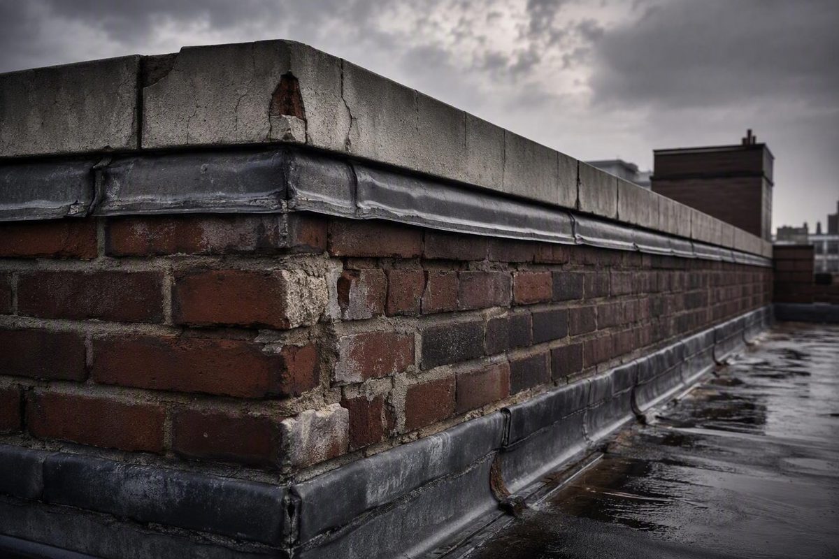
A parapet is easy to recognize but easy to underestimate. It is the wall or barrier that rises above a roof, terrace, balcony, walkway, bridge, or another exposed edge. On a modern building, that apparently simple wall may contribute to edge protection, conceal rooftop equipment, continue a fire-separation wall, shape the façade, and alter wind pressures around the roof perimeter.
A roof parapet is also one of the building envelope’s most demanding junctions. Roof membrane, wall cladding, insulation, air and vapor control, flashing, coping, anchors, joints, and drainage all converge in a narrow, exposed zone. Successful design therefore depends less on the parapet as an object than on how those elements work together as an assembly.
What Is a Parapet?
A parapet, also called a parapet wall, is a wall or barrier extending above the edge of a roof, terrace, balcony, walkway, bridge, or similar structure. The word can describe both a defensive wall and a low wall or railing at an exposed edge, reflecting its historic and modern uses (Merriam-Webster’s definition of parapet).
At a roof, the parapet may simply be the continuation of the exterior wall above the roof surface. It may instead continue a vertical feature such as a firewall or party wall. That distinction matters because the construction beneath the roof line influences the parapet’s structure, movement, control-layer transitions, and possible fire-separation role.
The word derives from the Italian parapetto, formed from terms associated with defending or covering the chest. Its origins lie in defensive architecture, where raised barriers sheltered people on walls and fortifications. The term later broadened to include protective and architectural barriers at exposed edges (an overview of parapet history and terminology).
The physical definition is deliberately broad. It describes what the element is and where it is located, not what performance it achieves. A low wall can be a parapet without satisfying the requirements applicable to fall protection. A roof-edge wall can be a parapet without having the construction or extension required of a firewall. The name alone also establishes nothing about structural capacity, anchorage, moisture resistance, or durability.
That distinction between form and verified performance is fundamental. Before relying on a parapet for safety, fire separation, wind resistance, or another technical purpose, designers must identify the applicable project criteria and verify the complete assembly against them.
What Parapets Do in Modern Construction
A parapet first defines an exposed edge. On an accessible roof or terrace, a properly designed parapet may form all or part of an edge-protection system. On a service roof, it may screen mechanical units, ducts, vents, or other equipment from street-level views. It can terminate the visual composition of a façade, carry decorative masonry or panels, or create the strong horizontal roofline associated with many commercial and urban buildings.
Some parapets have specialized fire-separation functions. A firewall or party wall may continue through and above the roof, but whether the extension forms part of a required fire-resistance system depends on the governing rules and the approved construction. Not every roof parapet is a firewall.
A parapet also changes roof-edge aerodynamics. Wind passing a building forms vortices near the perimeter and creates pressure differences across the roof assembly. An appropriately designed parapet can reduce those differences, but it does not eliminate the need to determine wind loads or to design the membrane, deck, coping, cladding, anchors, and connections accordingly (Building Science Corporation’s discussion of roof-edge wind effects).
One parapet may perform several functions at once:
- Define a roof, terrace, balcony, or walkway edge
- Contribute to an edge-protection system
- Screen rooftop equipment
- Continue a fire or party wall
- Alter roof-edge wind pressures
- Complete an architectural composition
- Support transitions between roofing and wall-envelope systems
These functions are not interchangeable. A wall high enough to screen equipment may still be unsuitable for fall protection. A substantial masonry wall may have no required fire rating. A parapet that changes wind flow may still have inadequate coping anchors. Each intended function requires its own criteria, details, and verification.
Traditional Types and Specialized Applications
Traditional parapet classifications describe appearance and form. They do not, by themselves, indicate structural strength, fire resistance, water tightness, or suitability as an edge-protection system.
Plain parapets are straightforward upward wall extensions, commonly finished with coping or another cap. They may look simple even when the concealed roof-edge construction is complex.
Embattled parapets are associated with battlements and crenellations. Their alternating raised and open portions originally supported defensive use. On later buildings, the same form may be entirely decorative.
Perforated parapets contain through-openings arranged as decorative patterns. Traditional examples include circles, trefoils, and quatrefoils. Those openings may affect wind, privacy, drainage, and edge-protection performance, so the visual classification is not a substitute for technical review.
Panelled parapets remain substantially solid but are ornamented with recessed, raised, square, oblong, or framed panels rather than through-openings.
These categories can overlap. An embattled parapet may also be panelled, for example. They are architectural descriptions rather than mutually exclusive construction systems (traditional parapet classifications).
Specialized applications introduce different priorities:
- Roof parapets combine structure, architectural finish, edge conditions, roofing transitions, drainage, and environmental exposure.
- Firewall parapets may continue a fire-resistance-rated wall above a roof, subject to the construction and extension rules applicable to the project.
- Bridge parapets may restrain pedestrians or vehicles and can also limit debris, views, or noise. Their design may fall under specialized transportation or pedestrian-restraint criteria rather than ordinary building-edge provisions.
- Fortification parapets shelter defenders and may include crenellations, embrasures, or firing steps.
A bridge barrier and a decorative roof parapet may share a name while having very different load cases, geometries, materials, and approval routes. “Parapet” identifies the broad family; use and governing criteria define the actual design problem.
Anatomy of a Roof Parapet
A roof parapet should be treated as an integrated roof-edge assembly, not as an isolated strip of masonry, concrete, or framing. The wall is only one part of a system that must resist project loads, control water and air, limit unwanted heat and vapor flow, accommodate movement, and coordinate with roof drainage.
A useful annotated section should identify at least the following:
- Structural wall, curb, or framed core
- Roof deck
- Roof insulation
- Roof membrane
- Membrane upstand or roof-to-wall transition
- Membrane termination or top wrap
- Concealed and exposed flashing
- Coping or cap
- Coping joints, cleats, anchors, and fasteners
- Inner and outer drip edges
- Cladding, veneer, or exposed masonry
- Movement and control joints
- Nearby drains, scuppers, gutters, and overflow routes
The most useful drawing does more than label materials. It traces the principal control layers from the roof field through the parapet and into the wall. The water-control layer should not end ambiguously at the roof edge. The air-control layer needs a sealed route across changes in substrate and geometry. Thermal insulation should be coordinated to reduce avoidable bridges. Vapor control requires an assembly- and climate-specific strategy rather than the indiscriminate addition of another membrane.
Continuity does not mean that every layer must follow the same route. A roof membrane might turn up the inboard face while a separate transition membrane connects the air-control layer across the deck edge. Insulation may pass inside, outside, or around the parapet structure. The objective is for every control function to have an intentional, constructible, and inspectable path.
A general installation sequence is:
- Complete and verify the supporting structure.
- Coordinate the roof and wall insulation.
- Install or connect the water-, air-, and vapor-control layers.
- Form the membrane upstand or approved roof-to-wall transition.
- Protect and terminate the membrane as detailed.
- Install concealed flashing, coping supports, and coping.
- Complete cladding, sealant, drainage, and adjacent finishes.
- Inspect concealed work before covering it, then inspect the completed interfaces.
This is coordination logic, not a universal specification. The approved roof and wall assemblies, product instructions, construction sequence, and project documents determine the actual work.
Coping anchors, railing posts, signs, screens, cables, and façade supports should be coordinated before the control layers disappear behind finishes.
Movement also needs a deliberate path. If membrane stress is trapped at the perimeter, the membrane may pull away from a transition, tear, or load the parapet. The detail should transfer intended forces to the supporting structure while accommodating compatible movement at joints and transitions.
Building-science guidance emphasizes both control-layer continuity and the need to prevent roof-membrane stress from concentrating at the perimeter (technical guidance on parapet control layers and membrane movement).
For design communication, an annotated section should show both materials and functions. Color-coded lines for water, air, vapor, and thermal control can reveal discontinuities that an ordinary black-and-white section may conceal.
How Parapets Keep Water Out
Effective parapet water management follows a layered sequence:
- Shed water from the top.
- Protect exposed joints and penetrations.
- Maintain concealed waterproofing continuity beneath them.
- Drain the roof without prolonged ponding.
A common design approach is to slope the top inward, toward the roof, where that arrangement is compatible with the approved coping and drainage design. Coping or capping protects the wall’s most exposed surface. Drip edges on both sides interrupt water tracking beneath the cap and help move runoff away from wall faces. Waterproofing beneath the coping supplies a second line of defense when exposed joints admit water.
The roof-deck-to-parapet intersection deserves particular attention because it combines a plane change, material transitions, movement, and often a membrane termination. Manufacturer-sponsored trade guidance identifies this junction as having especially high leak potential and recommends selecting membranes for the substrate, vertical application, temperature, moisture exposure, and final exposure conditions (trade guidance on waterproofing parapet walls).
Installation practices vary by system, but several principles recur:
- Substrates should be sound and prepared as required by the selected system.
- Masonry or weathered surfaces may require a compatible primer.
- Membrane laps should be oriented so water flows over rather than against them.
- Self-adhered sheets should be rolled where the product instructions require it, especially at overlaps and changes in plane.
- Terminations should be mechanically secured or otherwise completed as specified.
- Membranes, primers, sealants, coatings, and metals should be checked for chemical and physical compatibility.
Exposed sealant is a serviceable joint material, not a complete water-management strategy. Coping joints, corners, ends, elevation changes, anchors, railings, top penetrations, membrane terminations, scuppers, and roof-to-wall transitions all need explicit details. Concealed continuity provides redundancy when an exposed joint ages, moves, or is imperfectly installed.
Stone coping as a focused example
Stone coping illustrates why redundancy matters. Stone units are often secured with dowels that penetrate waterproofing below the coping. Sealing tightly around those dowels can be difficult. One enclosure-consulting approach is to install continuous metal through-wall flashing beneath the stone, with carefully located notches and sealed penetrations at the dowels. This does not eliminate the need for precise detailing; it adds another drainage plane beneath vulnerable sky-facing joints.
Joint materials involve tradeoffs. Mortar may crack as coping units move. Polyurethane sealant can provide useful tear resistance but may be more vulnerable to ultraviolet degradation. Silicone accommodates movement and resists ultraviolet exposure but may stain adjacent stone. Lead tees may suit some historic work but add cost and safe-handling considerations. The suitable choice depends on movement, climate, aesthetics, materials, and project conditions (stone-coping waterproofing guidance).
Wrap over the top or terminate below the coping?
There is no universal answer. Some assemblies carry a compatible membrane across the parapet top beneath the coping. Others turn the roof membrane up the inner face and terminate it below the coping or flashing, while a separate material protects the top.
The correct arrangement depends on:
- The tested or approved roof and wall assembly
- Substrate type and condition
- Membrane approval for the intended orientation and exposure
- Heat beneath metal coping
- Vapor behavior and drying direction
- Coping attachment and joint configuration
- Manufacturer instructions
- Project specifications
- Warranty conditions
- Governing project requirements
Practitioner guidance for some wood-framed details recommends a roof-membrane upstand of at least 12 inches, or higher where the project specifications require it, while also discouraging a TPO top wrap except under particular construction conditions. Those are system-specific recommendations, not universal code provisions (Hammer & Hand’s wood-parapet details).
Commercial construction guidance also cites 150 millimeters as a common example of an upstand above the finished roof while expressly noting that actual requirements vary. That figure is likewise illustrative rather than universal (parapet construction guidance).
A generic dimension should never replace the approved detail for the project.
Masonry, Concrete, and Wood-Framed Parapets
No parapet material is universally superior. Meaningful comparison focuses on how the complete assembly manages movement, wetting, drying, heat flow, waterproofing interfaces, and maintenance.
| Assembly | Likely movement | Moisture sensitivity | Drying strategy | Thermal-bridge concerns | Typical vulnerable interfaces | Specialist coordination |
|---|---|---|---|---|---|---|
| Brick or other unit masonry | Unit, mortar, slab, and coping movements may differ | Porous units and joints can absorb water | Drainage, evaporation, and any designed cavity path | Masonry and slab edges may bypass insulation | Coping joints, flashing, mortar cracks, membrane upturn | Mason, roofer, enclosure consultant, structural engineer |
| Cast-in-place concrete | Shrinkage, thermal movement, and cracking | Cracks, joints, and penetrations may admit water | Surface drainage and assembly-specific drying | The concrete edge can form a conductive path | Construction joints, cracks, anchors, roof transition | Structural engineer, concrete contractor, roofer, enclosure consultant |
| Wood-framed | Framing shrinkage and differential movement | Sensitive to bulk water and condensation | Vented or unvented strategy designed for the assembly and climate | Studs, plates, fasteners, and gaps in insulation | Top penetrations, sheathing joints, framing connections, membrane termination | Architect, enclosure consultant, framer, roofer |
| Metal-framed | Thermal expansion and connection movement | Performance depends on corrosion protection and condensation control | Drained, ventilated, or sealed strategy as designed | Metal members and clips can bridge insulation | Fasteners, sheathing transitions, cap attachments | Architect, structural engineer, enclosure consultant |
| Prefabricated system | Product- and connection-dependent | Joint and interface performance governs exposure | Product-specific | Connections and supports require analysis | Module joints, roof tie-in, façade tie-in, anchors | Manufacturer, designer, roofer, structural engineer |
Brick and other masonry parapets
Masonry parapets are exposed to wind-driven rain and wetting from above. Units and mortar joints may be porous; mortar can shrink; and the roof slab, wall, and coping may move differently. In cold climates, retained water can contribute to freeze-thaw deterioration. Coping, flashing, membrane integration, and movement joints therefore matter as much as the brick or block itself.
The parapet may also interrupt otherwise continuous insulation. Extending a masonry wall directly above a concrete deck or roof structure can create a conductive path unless the thermal-control strategy is deliberately carried through the junction. Thick masonry alone does not establish adequate thermal or condensation performance.
Commercial masonry guidance identifies thermal cycling, differential slab-to-wall movement, mortar shrinkage, porous materials, freeze-thaw exposure, and roof-membrane integration as recurring concerns. Because the source also markets alternative parapet systems, its general performance claims should be treated cautiously rather than as comparative proof (brick-parapet construction and failure overview).
Cast-in-place concrete parapets
Concrete can provide an integral structural edge, but its performance depends on project-specific reinforcement, formwork, consolidation, curing, joints, and crack control. Waterproofing must accommodate construction joints, cracks, anchors, and changes of plane.
Dimensions and reinforcement cannot be selected from a generic parapet description. They require design for the actual geometry, materials, support conditions, and loads.
Wood-framed parapets
Wood-framed parapets can be exposed on the roof side, façade side, and top. Air leakage from conditioned space may carry moisture into cold cavities, while top penetrations and framing connections can create direct paths between the interior and the parapet. Careful air sealing, membrane transitions, insulation, and cap detailing are therefore essential.
Some practitioner details recommend cavity ventilation, additional high and low vents for taller cavities, and avoidance of balloon framing and top penetrations where possible. These are assembly-specific approaches, not universal rules. Whether a cavity should be vented, sealed, or designed to dry in a particular direction depends on climate, roof and wall configuration, materials, and interior humidity.
Other systems
Metal-framed and prefabricated parapets are additional options.
Claims that one system is inherently faster, more durable, more thermally efficient, or less failure-prone than another require comparative evidence. Those conclusions should not be inferred from material type alone.
Why Parapets Crack, Leak, and Deteriorate
Parapet symptoms often appear far from their source. Water entering an open coping joint may move through a cavity, follow flashing or structural surfaces, wet roof insulation, and emerge at an interior ceiling.
Common entry points include:
- Open or deteriorated coping joints
- Loose coping or failed attachment points
- Railing, screen, sign, or equipment penetrations
- Cracked units, mortar, stone, or concrete
- Defective through-wall or cap flashing
- Incomplete membrane terminations
- Failed roof-to-wall transitions
- Open movement joints
- Scupper and drain interfaces
Movement is a frequent contributor. Solar heating and nighttime cooling cause coping, masonry, concrete, framing, and membranes to move at different rates. Mortar may shrink. Roof slabs may move differently from walls. Roof membranes may impose stress at the perimeter if movement is restrained or not properly transferred. Visible results can include cracked joints, displaced caps, separated flashing, or torn membrane.
Water can then amplify deterioration. Porous or cracked masonry may absorb moisture. In cold climates, repeated freezing of retained water can damage saturated units and mortar. Severity depends on material properties, saturation, exposure, detailing, and climate; a visible crack alone does not establish the extent of concealed deterioration.
Discontinuous control layers create other paths. An air-control gap may allow humid interior air to reach cold surfaces. Poorly coordinated vapor control may restrict drying or increase condensation risk.
Drainage matters as well. Blocked drains, scuppers, gutters, or overflow routes can leave water standing against seams and flashings.
| Symptom | Plausible causes to investigate | Inspection points | Response priority | Appropriate specialist |
|---|---|---|---|---|
| Open coping joint | Joint deterioration, thermal movement, displaced unit | Joint condition, adjacent coping, concealed flashing | Prompt if water is entering or coping is loose | Enclosure consultant, mason, roofer |
| Interior damp patch | Coping leak, membrane transition, flashing defect, condensation | Roof edge, moisture pattern, insulation, control-layer continuity | Prompt investigation | Enclosure consultant, roofer |
| Masonry crack | Shrinkage, differential movement, thermal cycling | Pattern, displacement, recurrence, surrounding joints | Depends on movement and displacement | Structural engineer, mason |
| Bulging or leaning parapet | Loss of stability, restraint problems, material deterioration | Alignment, anchorage, backing wall, loose units | Urgent | Structural engineer, mason |
| Efflorescence or staining | Repeated wetting, salt transport, failed drip or coping | Top slope, drips, joints, flashing, drainage | Investigate source and extent | Mason, enclosure consultant |
| Blistered or detached membrane | Moisture, adhesion loss, movement, or substrate problems | Seams, insulation, perimeter restraint, termination | Prompt roof assessment | Roofer, enclosure consultant |
| Ponding near the parapet | Blocked drainage, poor slope, or changed roof elevations | Drains, scuppers, overflow route, roof surface | Prompt drainage review | Roofer, architect |
| Loose coping or masonry | Attachment failure, movement, or material deterioration | Unit stability, attachment, wall condition below | Urgent where material could fall | Structural engineer, mason |
| Mold or musty odor | Persistent wetting, condensation, or limited drying | Hidden cavities, interior air paths, roof and wall transitions | Prompt moisture investigation | Enclosure consultant |
Diagnosis should precede treatment. Sealant may be appropriate for a stable, properly designed moving joint but ineffective over displaced masonry. Repointing may restore deteriorated mortar while leaving failed concealed flashing untouched. Membrane work may stop one leak while a loose coping unit remains hazardous. Reconstruction may be necessary in some cases, but visible cracking alone does not determine the repair scope.
Inspection, Maintenance, and Repair Decisions
Inspection should connect exterior conditions, roof drainage, and interior symptoms rather than treating each in isolation. Record observations with dated photographs, locations, weather conditions, and notes on whether each symptom is new, stable, recurring, or changing.
A practical checklist includes:
- Displaced, rocking, cracked, or missing coping
- Open coping joints
- Split, debonded, missing, or hardened sealant
- Loose brick, block, stone, panels, or trim
- Crumbling or washed-out mortar
- Vertical, horizontal, stepped, or diagonal cracks
- Bulging, leaning, bowing, or other displacement
- Rust staining or visible metal deterioration
- Efflorescence and recurring façade staining
- Peeling paint, coatings, or interior finishes
- Damp patches on roof, wall, or ceiling surfaces
- Mold growth or musty odors
- Membrane splits, blisters, open laps, or failed terminations
- Loose flashing, cleats, fasteners, or counterflashing
- Debris in drains, scuppers, gutters, and overflow routes
- Ponding near the parapet
- New penetrations or equipment attachments
- Deterioration around railings, signs, screens, and anchors
Some findings can enter routine maintenance planning, such as intact but weathered sealant, minor coating wear, or debris that can be removed safely without disturbing the assembly. Even then, the cause and safe access method matter.
Other conditions call for prompt escalation. A bulging or leaning wall, significant movement, displaced coping, or loose masonry above occupied or public space should receive professional evaluation without delay. Restricting or protecting the area below may be a prudent interim safety measure until the condition is assessed; surface sealant must not be treated as a way to stabilize loose material (reported parapet warning signs and repair indicators).
Localized sealing or repointing may be unsuitable when the underlying cause is:
- Structural movement or inadequate restraint
- Failed concealed flashing
- Saturated insulation, sheathing, or masonry
- Deteriorated attachment components
- Broad membrane discontinuity
- Incompatible materials
- Blocked or poorly coordinated drainage
- Freeze-thaw deterioration behind the face
- Condensation caused by air- or thermal-control defects
The appropriate specialist depends on the problem:
- A qualified mason can assess masonry units, stone, and mortar.
- A roofer can examine membranes, seams, flashings, and drainage.
- A building-envelope consultant can investigate water, air, vapor, and thermal paths across systems.
- A structural engineer should assess instability, anchorage, loading, or significant displacement.
- An architect can coordinate repair design across the roof, wall, structure, and appearance.
- A local code official can clarify adopted administrative and technical requirements but does not replace the project designer.
Nor should a repair be called permanent merely because the visible symptom disappears. Record completed work, retain photographs and detail drawings, and observe the repaired area over time.
Code Questions and a Practical Design Checklist
Parapet requirements cannot be resolved generically. The relevant questions may include:
- What height and geometry apply to the intended use?
- What structural support, reinforcement, and anchorage are required?
- Which wind, impact, seismic, or other loads apply?
- How must coping, cladding, and attachments be secured?
- Does the edge require a regulated guard or another protection system?
- Are opening or climbability limitations applicable?
- Does the parapet form part of a fire-resistance-rated wall?
- Must a firewall or party wall extend above the roof?
- What membrane upstand or termination is approved?
- How are primary drainage and overflow handled?
- What inspections, reports, or acceptance procedures apply?
- How will maintenance personnel reach the assembly safely?
The answers can change with occupancy, roof accessibility, building type and height, structural system, climate, materials, loads, tested assemblies, project documents, and jurisdiction. A parapet on an inaccessible service roof is not necessarily governed like one bordering an occupied terrace. A decorative opening may be acceptable in one context and unsuitable at an edge subject to regulated opening limitations.
Most importantly, a parapet that contributes to fall protection is not automatically a compliant guard. Its suitability must be established under the terminology and requirements adopted for the particular project.
The checklist below is a design-review aid, not a code summary or substitute for professional design:
- [ ] Intended functions are explicitly defined.
- [ ] Structural support, reinforcement, and anchorage are verified.
- [ ] Applicable loads are coordinated with the roof edge and coping.
- [ ] Edge-protection and accessibility questions are resolved.
- [ ] Any fire-separation role is tied to an approved assembly.
- [ ] Water, air, vapor, and thermal-control layers are traced.
- [ ] Coping slope and inner and outer drip edges are shown where appropriate.
- [ ] Concealed waterproofing beneath coping is detailed.
- [ ] Coping joints, corners, ends, and elevation changes are detailed.
- [ ] Scuppers, primary drains, and overflow routes are coordinated.
- [ ] Anchors and penetrations have explicit waterproofing details.
- [ ] Membrane terminations or top wraps match the approved system.
- [ ] Differential movement is accommodated.
- [ ] Sealants, membranes, primers, coatings, metals, and substrates are compatible.
- [ ] Drainage paths remain accessible for maintenance.
- [ ] Construction sequencing avoids damage to completed control layers.
- [ ] Concealed-stage and final inspections are assigned.
- [ ] Project-specific testing and acceptance criteria are identified.
Practitioner and manufacturer details can inform design, but their dimensions are not binding merely because they appear in a guide. A stated membrane upstand, cap gauge, lap width, venting arrangement, or joint material becomes project-specific only when it is compatible with the assembly and adopted through the specifications, approved submittals, manufacturer requirements, tested system, or governing rules.
For regulated or safety-critical decisions, consult the currently adopted local building and fire codes, applicable structural and transportation standards, approved roof and wall assemblies, product instructions, project specifications, and qualified professionals. This article does not establish the legal requirements for any jurisdiction or project.
Frequently Asked Questions
What is the difference between a parapet and a guardrail?
A parapet is identified by its physical form and location: it is a wall or barrier extending above an exposed edge. Whether that parapet also qualifies as a regulated guard or another required edge-protection system is a separate, project-specific question.
A short decorative wall remains a parapet even when it is unsuitable for fall protection. Where people can approach the edge, the adopted terminology and performance criteria must be checked.
How tall does a parapet need to be?
There is no universal parapet height. The answer depends on its intended function, roof accessibility, occupancy, building type, edge-protection criteria, fire-separation role, structural stability, wind exposure, approved design, and jurisdiction.
A parapet used only as an architectural roof-edge feature may have different criteria from one bordering an occupied terrace or continuing a firewall. Generic figures from product literature and online guides should not replace current project documents and locally adopted requirements.
Does a roof membrane always need to wrap over the top of a parapet?
No. Some assemblies carry a compatible membrane across the top beneath the coping. Others turn the roof membrane up the inner face and terminate it below coping or flashing, with separate materials protecting the top.
The correct arrangement depends on the tested or approved assembly, substrate, membrane application limits, heat exposure, vapor behavior, coping attachment, manufacturer instructions, warranty conditions, and project specifications. Guidance discouraging a wrap in one assembly does not prohibit it everywhere, just as a preferred wrap detail does not make it universally required.
Where do parapet leaks most often begin?
Common starting points include coping joints, corners, attachment points, top penetrations, cracks, flashing defects, membrane terminations, and the roof-deck-to-wall transition. Water may then travel through concealed cavities, masonry, insulation, or structural interfaces before appearing indoors.
Because the visible stain may not align with the entry point, diagnosis should examine the coping, wall, membrane, drainage, and interior symptoms together. Exposed sealant should not be assumed to be the assembly’s only defense.
When does a damaged masonry parapet need professional evaluation?
Prompt evaluation is appropriate when there is bulging, leaning, significant displacement, loose brick or stone, displaced coping, widening cracks, recurring leakage, extensive mortar loss, or deterioration above occupied or public areas.
Professional diagnosis is also advisable when earlier repairs have failed, concealed flashing may be defective, materials appear persistently wet, or it is unclear whether cracking reflects joint movement or broader displacement. Depending on the symptoms, the evaluation may involve a mason, roofer, building-envelope consultant, architect, or structural engineer.
A parapet is both an edge wall and a coordinated assembly. The three practical priorities are straightforward: identify every function it is expected to perform, preserve control-layer continuity from the roof through the flashing and coping, and investigate cracking, dampness, movement, or loose materials before selecting a repair.
Dimensions, structural capacity, edge-protection performance, and fire requirements must always be checked against current project documents, approved assemblies, manufacturer instructions, adopted local rules, and advice from qualified professionals.