
Z Bar Flashing: How It Works and What Changes by Joint
Measure the upper leg for the drainage layer, the middle depth for the joint or projection and the lower leg for the drip edge before choosing a profile.
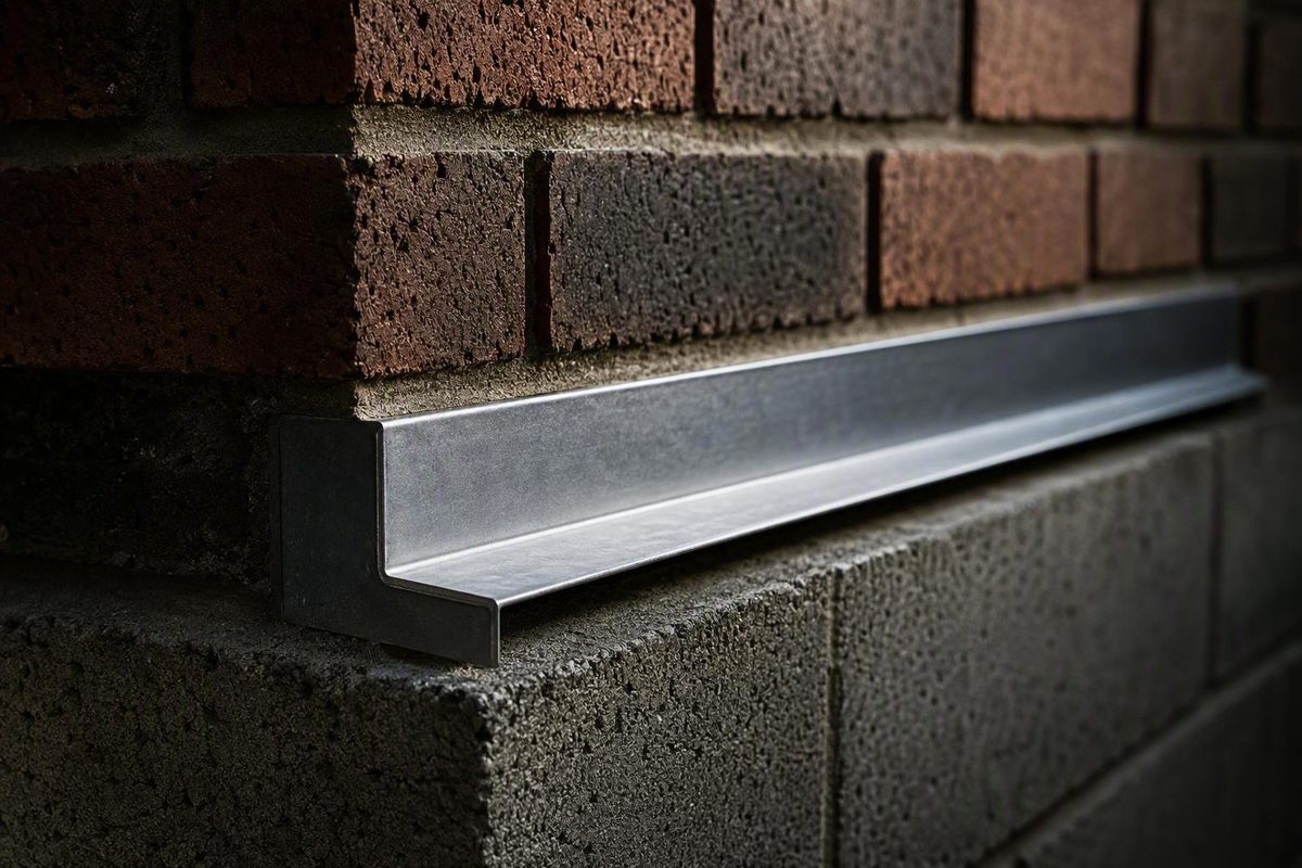
Z-bar flashing is easy to recognize but easy to mis-specify. Its stepped cross-section can carry water across a horizontal joint and release it in front of the materials below. Yet “Z bar” describes a family of bent profiles—not one standardized size, metal, or installation detail.
This guide is best used as a profile-selection and purchasing framework. It does not provide an approved construction detail for every siding joint, opening, ledger, or roof intersection. Start with the assembly, identify where water must go, and measure every leg of the required profile. Then compare materials, finishes, section lengths, and fabrication options against the applicable product and system instructions.
What Z-bar flashing is and how its three-part profile sheds water
Z-bar flashing, commonly shortened to Z flashing, is a bent profile used to direct water outward at horizontal joints and exterior transitions. The characteristic shape comes from two bends that create a stepped section resembling the letter Z.
A typical profile has three functional parts:
- Upper leg: The vertical portion that integrates behind the upper cladding, trim, or water-resistive layer.
- Middle leg: The portion that crosses or caps the horizontal joint, offset, or projecting material.
- Lower leg: The downward portion that extends in front of the lower component and acts as a drip edge.
Water descending over or behind the upper material should encounter the upper leg, move across the joint-covering middle leg, and leave from the lower edge in front of the assembly. The middle portion therefore needs to drain toward the exterior. The evidence does not establish one minimum slope suitable for every siding, opening, ledger, or roofing system; the applicable product and assembly instructions control that detail.
A hem or small kick may be formed at the lower edge, but it does not alter the basic drainage sequence:
             WALL SIDE                         EXTERIOR SIDE

 Upper cladding or drainage layer
             │
             │  Water direction ↓
             │
             │  UPPER LEG
             │  │
             │  └──────────────→  MIDDLE LEG
             │                    covers joint and drains outward
 Lower part  │                                  │
 being capped│                                  │ LOWER DRIP LEG
             │                                  ↓
                                                Water released
                                                in front
The name Z flashing does not identify a standard set of dimensions. One profile may have a shallow middle leg for a thin panel, while another must bridge deep trim, blocking, furring, or insulation. Upper-leg height, lower-leg length, material thickness, finish, hem, and overall section length can also vary.
That variability is the central selection issue: the required geometry comes from the joint, not from the product name.
Where Z flashing is used—and where the details begin to differ
Z flashing appears at several exterior transitions, but the surrounding layers differ by application. A profile suitable for a horizontal panel joint should not automatically be carried over to an opening, deck ledger, chimney, or roof intersection.
Horizontal siding and panel transitions
At a horizontal break in siding or panels, the flashing commonly caps the top of the lower component. The middle leg bridges its thickness or offset, the lower leg drops in front, and the upper leg integrates behind the upper cladding or relevant drainage layer.
This arrangement gives water descending from above a route over the joint instead of into it. The exact sequence still depends on the wall system, including whether it uses lap siding, panels, furring, a rainscreen cavity, exterior insulation, or another configuration.
Heads of windows and doors
Above an opening, a Z-shaped profile may serve as head or cap flashing. Its purpose is to direct water over and in front of the head trim or opening rather than allowing water to move behind it.
That does not make every stock Z bar a suitable window or door cap. The required profile may be affected by trim depth, membrane sequencing, jamb interfaces, end conditions, drainage clearance, and the opening manufacturer’s flashing system. A generic cross-section cannot replace the instructions for the particular window, door, cladding, and water-resistive barrier.
Trim, band boards, and deck ledgers
Band boards and projecting trim create horizontal surfaces that must be connected to the wall’s drainage path. In these locations, the middle leg is sized to cover the projection while the upper and lower legs establish the intended drainage sequence.
At a deck ledger, the flashing must bridge the wall-to-ledger transition and direct water away from that interface. Retail catalogs list dedicated deck-ledger profiles alongside window caps and other flashing types, demonstrating that related shapes are sold for distinct applications (compare Lowe’s Z-flashing categories and applications). The metal profile is only one part of the surrounding wall and ledger detail; it should not be treated as a complete deck-water-management system.
Selected roof-to-wall transitions
A Z-shaped component may appear where a roof meets a wall, but the intersection is an assembly rather than a single strip of metal. Depending on the condition, it may involve headwall or step flashing, base flashing, counterflashing, blocking, a water-resistive barrier, and clearance beneath the wall covering.
Terminology is particularly important here. A stock siding Z bar should not automatically be substituted for:
- Window cap flashing
- Step flashing
- Headwall or base flashing
- Chimney counterflashing
- Masonry through-wall flashing
- A project-specific roof-to-wall transition
These components perform related water-management functions, but their shapes and positions within the assembly differ. Treat siding joints, opening heads, deck ledgers, and roof-to-wall intersections as separate conditions rather than assuming one convenient arrangement applies to all four.
How to measure and specify a Z-flashing profile
Do not order Z flashing from a single label such as “1/2-inch Z bar” unless the product drawing defines exactly what that dimension represents. Specify all three legs and confirm how the manufacturer identifies them.
A reliable sizing workflow begins with three project measurements.
1. Determine the upper-leg requirement
Measure the height required to integrate the profile with the drainage layer and upper cladding. Account for the locations of the water-resistive barrier, flashing membrane, siding edge, fasteners, furring, and required clearances.
A longer upper leg is not automatically better. It must fit behind the relevant layers without interfering with laps, fastening, or adjacent components.
2. Measure the middle offset or cap depth
The middle dimension is commonly driven by the installed thickness or projection of the component being capped, such as:
- Siding or a wall panel
- Window or door trim
- A band board
- A deck ledger
- Roof-to-wall blocking
- Exterior insulation or furring
Measure the completed condition rather than relying only on the nominal name of a board, trim piece, or panel. Include shims, membranes, coatings, and other layers that materially affect the offset.
The middle leg must reach across the joint and drain outward. A profile that is too shallow may not cover the projection; one that is excessively deep may fit poorly or create an unintended shelf.
3. Determine the lower drip-leg requirement
The lower leg must project in front of the lower component and remain able to act as the intended drip edge. Confirm whether the proposed product has a straight edge, hem, or kick and whether that configuration fits the required clearance.
Once all three dimensions are known, compare them with the manufacturer’s drawing.
Tamlyn, for example, publishes five nominal A/B/C combinations within one Z-flashing family:
| Example item | A | B | C |
|---|---|---|---|
| VZB516 | 1-3/16 in. | 5/16 in. | 1/2 in. |
| VZB516W | 4 in. | 5/16 in. | 1/2 in. |
| VZB388 | 1-5/8 in. | 3/8 in. | 1/2 in. |
| VZB12 | 1 in. | 1/2 in. | 1/2 in. |
| VZB58 | 1-3/8 in. | 5/8 in. | 1/2 in. |
These are manufacturer-specific nominal dimensions and must be read using Tamlyn’s profile orientation; they are not universal application sizes (review Tamlyn’s profile drawing and nominal table).
Retail descriptions may be less complete. A listing called “1/2-inch Z bar” might refer to the middle offset, a vertical leg, or a local catalog convention. Color-coded product names can be equally ambiguous because the listing may not explain whether the color indicates a finish or a size. The individual profile drawing—not the shortened product name—should control the purchase.
Use a worksheet before requesting a quote or placing an order:
| Specification field | Project requirement |
|---|---|
| Application and assembly | |
| Upper-leg requirement | |
| Middle offset or cap depth | |
| Lower drip-leg requirement | |
| Hem, kick, or edge configuration | |
| Metal or other material | |
| Material thickness | |
| Coating, primer, or finish | |
| Actual section length | |
| Total linear run | |
| Corners and terminations | |
| Required seam lap and treatment | |
| Governing manufacturer instructions | |
| Local requirements to verify |
Assign a profile to an application only when its geometry and documentation support that use. Similar dimensions alone do not establish that two products have the same intended function.
Choosing among aluminum, galvanized steel, and other materials
Aluminum and galvanized steel are the two materials most consistently represented in the supplied commercial catalogs. Selected sources also mention copper, stainless steel, vinyl, and zinc-coated products, but those options should not be treated as equally common or interchangeable.
Material selection should consider:
- Weather exposure and retained moisture
- Adjacent metals and coatings
- Contact with treated wood or masonry
- The cladding, roofing, or opening system
- Required material thickness
- Paintability and finish
- Availability of the required profile
- Manufacturer-system requirements
- Whether the flashing will be stock, field-bent, or custom fabricated
- Compatibility with fasteners, membranes, sealants, and substrates
As a bounded product example, Tamlyn lists its primed version as 0.019 ± 0.003-inch galvanized steel and its color-matched version as 0.019 ± 0.003-inch aluminum painted on both sides. Those figures describe Tamlyn’s listed products, not a general thickness requirement for all Z flashing (see Tamlyn’s material specifications).
Aluminum is available in coordinated finishes and custom-formed profiles, while galvanized steel is offered in numerous stock configurations. The choice should rest on documented suitability for the assembly—not on an unsupported assumption that one material is always stronger, more durable, or more corrosion resistant.
Lowe’s recommends using the same type of fastener material as the flashing. That is limited retailer guidance, not a complete compatibility rule (see Lowe’s Z-flashing guidance).
Verify the full combination through the applicable flashing, cladding, roofing, fastener, sealant, and substrate instructions. Conditions involving dissimilar metals or chemically treated materials require particular attention.
Retail filters may classify products as “paintable,” “rust resistant,” or “corrosion resistant.” Home Depot, for example, provides aluminum and galvanized-steel filters within its Z-bar category (see the retailer’s Z-bar flashing classifications). These labels help shoppers navigate a catalog, but they are not comparative performance evidence or proof that a product suits a particular assembly.
The completed condition is affected by exposure, cutting, coating damage, storage, installation, maintenance, and contact with surrounding materials.
Stock lengths, hems, finishes, and custom-bent profiles
Stock Z flashing is generally the simplest option when a documented profile matches the joint. Commercial listings commonly include 8-foot and 10-foot sections, although shorter lengths are also sold. Tamlyn lists its standard profiles at 8 feet, while Ashby Lumber lists both 8-foot and 10-foot products (compare Ashby Lumber’s listed lengths and profiles).
These listings also show why a category name cannot replace a drawing. Several products are identified by one prominent size without clearly defining every leg in the category description.
Custom-bent flashing may be worth discussing with a fabricator when:
- The required middle offset does not match a stock profile.
- The upper and lower legs need an uncommon combination.
- A finish must coordinate with the cladding.
- Existing construction has an irregular but measurable offset.
- Project documents require a particular edge, hem, material, or thickness.
- The required profile is unavailable through local stock.
Custom fabrication is not the same as improvisation. The fabricator needs a cross-section showing each leg, bend direction, material, thickness, finish, edge treatment, and applicable tolerances. Curved, arched, or uneven transitions may require a different flashing strategy instead of a conventional straight Z section.
Commercially available configurations include hemmed, extruded, primed, and color-matched products. These are options rather than universal upgrades. Confirm the precise profile shown for the item being ordered. Tamlyn, for example, says a hem may be requested with primed material while also stating that its standard colors include a hem, so the actual ordered configuration needs verification.
Actual section length also matters. Trim Bender lists nominal 4-, 6-, and 8-foot custom aluminum offerings with corresponding actual lengths of 47, 72, and 94 inches. The seller also states that its custom products are non-returnable, non-exchangeable, and non-refundable (review Trim Bender’s listed lengths and custom-order terms). Verify actual rather than nominal length before calculating quantities.
A practical quantity method is:
- Measure the total linear run.
- Divide the run by the actual available section length.
- Add material for the specified laps between sections.
- Account for inside and outside corners.
- Include ends and terminations.
- Allow for cuts, unusable offcuts, and reasonable project waste.
- Round up to whole sections.
The lap allowance must come from the applicable assembly detail. Do not base an evergreen specification on current inventory, prices, ratings, shipping times, or seller warranty language; those details can change and do not establish technical suitability.
Installation principles: drainage sequence before fasteners and sealant
Installation is best understood as a sequence of water-shedding layers, not as a universal set of fastening steps. Fastener and sealant decisions come after the drainage path has been resolved.
The central principle is a shingle lap: upper layers direct water over lower layers. In a typical wall transition, the upper leg of the Z flashing integrates behind the upper cladding or water-resistive layer. The middle leg crosses the joint and drains outward. The lower leg remains in front of the lower component so water can leave from its edge.
Reverse laps undermine that sequence. Examples include:
- Directing the upper drainage layer behind the wrong face of the flashing
- Pitching the middle leg toward the wall
- Covering or sealing the lower edge so water cannot escape
- Terminating the flashing without resolving corners or ends
The lower leg must remain able to function as a drip. Burying it in sealant or blocking it with another component can interfere with the intended release of water. Required drainage spaces and clearances must remain open after finishes are installed.
Adjacent sections need an assembly-appropriate lap and joint treatment. Trex Seal gives a 2-to-3-inch overlap as general commercial guidance, but that range is not a universal requirement; the applicable siding, roofing, opening, or wall-system detail may require another lap or connection method (see Trex Seal’s joining guidance).
Fastening guidance varies with the assembly. General commercial instructions may say to secure the flashing, while one roof-to-wall detail recommends that flashing behind the wall covering remain free rather than being fastened to the wall. These positions address different conditions and should not be converted into one universal rule.
Fastening location and spacing cannot be selected responsibly without knowing the cladding, roofing, substrate, flashing profile, exposure, and manufacturer instructions. Fasteners and sealants are secondary detailing components; they cannot correct:
- An inward-sloping middle leg
- A reverse lap
- An upper leg placed outside the intended drainage sequence
- A blocked lower drip edge
- Insufficient clearance
- Inadequate section laps
- Missing counterflashing
- Unresolved corners, ends, or penetrations
Before installation, verify:
- The approved profile drawing and orientation
- The drainage-plane sequence
- Required clearances
- Permitted fastening locations and spacing
- Seam-lap and joint-treatment requirements
- Inside and outside corner details
- End dams, ends, and terminations
- Compatibility among metals, coatings, fasteners, sealants, and substrates
- Requirements for the cladding, roofing, opening, ledger, and water-resistive-barrier systems
- Applicable local requirements
Cut sheet metal can have sharp edges, so handling and cutting precautions appropriate to the material are necessary (Trex Seal also notes the sharp-edge hazard). Work requiring access beyond the installer’s equipment, experience, or project authorization should be assigned to an appropriately qualified contractor.
Roof-to-wall and masonry intersections need assembly-specific detailing
A stock Z bar is not, by itself, a complete answer where a roof meets siding, stucco, brick, or stone. These intersections may require several coordinated components:
- Headwall or step flashing
- Base flashing
- Counterflashing
- A Z-shaped through-wall component
- Blocking or backing
- A water-resistive barrier
- Drainage space
- Clearance beneath the wall covering
The components must be sequenced so water leaving the wall is discharged over the roof-side flashing rather than behind it.
One RoofKey detail proposes vertical blocking at the intersection, places Z-bar flashing behind the water-resistive barrier, and extends it over headwall or step flashing. Its source-specific recommendations include at least 3 inches up the wall, at least 3.5 inches down the blocking, and 1.5 inches between the roof and wall covering, while noting that some manufacturers require 2 inches (review RoofKey’s proposed roof-to-wall detail).
Those dimensions are recommendations for that author’s proposed arrangement—not universal code requirements. They should not be transferred automatically to another cladding, roof system, climate, or jurisdiction. The broader lesson is to coordinate the wall drainage plane, roof flashing, backing, and wall-covering clearance as one assembly.
Brick intersections
At a brick wall, counterflashing may be inserted into a mortar joint or a cut groove and then sealed. The metal insertion creates a physical interface with the masonry; the sealant closes the joint instead of serving as the only line of defense.
An exposed surface bead alone is more vulnerable because sealant can dry, shrink, crack, separate, or contain gaps. InterNACHI’s inspection guidance contrasts sealant-dependent conditions with counterflashing inserted into mortar joints or grooves (see its brick and stone counterflashing examples).
Stone intersections
The same general principle applies to stone: the counterflashing should extend behind the wall covering while preserving the required space above the roof. Irregular surfaces and different veneer systems can make this substantially more complex than a simple brick reglet.
Through-wall flashing versus surface mounting
Reglet-inserted counterflashing is secured into a joint or groove and protects the upper edge of base or step flashing. A surface-mounted strip depends more heavily on its upper seal and may allow water behind it if the masonry becomes saturated.
IIBEC defines counterflashing as an upper layer protecting the edge of base flashing and discusses through-wall and reglet-inserted approaches in contrast with vulnerable surface-mounted chimney conditions (read IIBEC’s counterflashing discussion).
These masonry sources discuss counterflashing and through-wall flashing; they do not define a standard masonry product called Z-bar flashing. A component may have a Z-shaped section without making “Z bar,” “counterflashing,” and “through-wall flashing” interchangeable terms.
Retrofits, chimneys, complex corners, curved surfaces, and conditions requiring removal of existing roofing or masonry warrant manufacturer-specific or professional design review. The work must account for what lies behind the visible surface rather than merely covering the exterior joint.
A practical buying and inspection checklist
Before ordering, convert the joint into a written specification instead of searching by product name alone.
Purchasing checklist
- [ ] Identify the exact application and assembly.
- [ ] Draw the intended direction of water movement.
- [ ] Record the upper-leg dimension.
- [ ] Record the middle offset or cap depth.
- [ ] Record the lower drip-leg dimension.
- [ ] Distinguish nominal dimensions from actual dimensions.
- [ ] Confirm the drawing’s A/B/C orientation.
- [ ] Specify the approved material.
- [ ] Confirm material thickness.
- [ ] Confirm coating, primer, or finish.
- [ ] Confirm whether the edge is straight, kicked, or hemmed.
- [ ] Record the actual section length.
- [ ] Calculate quantity using verified laps, corners, terminations, and waste.
- [ ] Review custom-product return and exchange terms.
- [ ] Obtain the relevant manufacturer documentation.
- [ ] Verify compatibility with fasteners, sealants, substrates, and adjacent materials.
- [ ] Confirm installation requirements before purchase.
Compare profile drawings rather than relying on retailer category names, color-coded descriptions, or filters. Retail assortments demonstrate that materials and profiles vary; they do not determine suitability for a particular joint.
After installation, the following conditions warrant comparison with the project drawings and manufacturer instructions:
- A middle leg that slopes inward
- An upper leg outside the intended drainage sequence
- A buried, sealed, or blocked lower drip edge
- Open or poorly treated seams
- Visible corrosion or damaged coatings
- Inadequate roof-to-wall-covering clearance
- Missing or incomplete counterflashing
- Surface sealant used as the only apparent defense
- Unresolved corners, ends, or penetrations
- Fasteners placed where the approved detail requires movement
Not every item proves that a leak exists. A proprietary system may address a condition in another documented way. These are reasons to stop and compare the work with the approved documents rather than relying on appearance alone.
Use this final decision sequence:
- Identify the assembly.
- Draw the layered drainage path.
- Measure all three profile legs.
- Select a documented material, thickness, and finish.
- Plan section lengths, laps, corners, and terminations.
- Verify fastening, sealant, clearance, and installation requirements.
- Order only after the profile drawing and system documentation agree.
The product label should come last. Z-bar flashing supports effective drainage only when integrated correctly with the surrounding cladding, roofing, water-resistive barrier, opening system, ledger detail, or counterflashing. Final dimensions, fastening, laps, clearances, corners, and sealants must be checked against the applicable manufacturer instructions and local requirements.
Frequently asked questions
Are Z bar flashing and Z flashing the same thing?
Usually, yes. Commercial references commonly use Z bar flashing, Z-bar flashing, and Z flashing for the same general stepped profile.
The shared name does not make every product interchangeable. Confirm the drawing, dimensions, material, finish, and intended application.
How do I know what size Z flashing to buy?
Measure the upper leg needed for integration with the drainage layer, the middle depth needed to cap the joint or projection, and the lower leg needed to form the drip edge.
Compare all three measurements with the manufacturer’s drawing. Do not assume a retailer’s single size label identifies a particular leg, and verify whether each published dimension is nominal or actual.
Should I choose aluminum or galvanized-steel Z flashing?
Choose according to the complete assembly rather than a general material ranking. Consider profile availability, thickness, finish, exposure, adjacent metals, treated wood, substrate, fasteners, sealants, and the governing product instructions.
Both materials are commonly marketed. Neither is universally superior or automatically compatible with every surrounding component.
How much should two sections of Z flashing overlap?
There is no universal lap for every application. One commercial guide gives a 2-to-3-inch range, but the applicable cladding, roofing, opening, or wall-system detail may require something different.
Confirm the lap and joint treatment before calculating quantities or cutting sections.
Can ordinary Z-bar flashing be used as masonry counterflashing?
Not automatically. Masonry counterflashing must protect the upper edge of the roof-side flashing and integrate appropriately with the brick, stone, mortar joint, reglet, or through-wall assembly.
A stock siding Z bar may have the wrong dimensions, material, edge configuration, or attachment method. For brick, stone, chimneys, and roof-to-masonry retrofits, use a detail prepared for that assembly and verify it against the applicable roofing, masonry, flashing, and local requirements.