
Brick-to-Brick Wall Ties Vary by Wall Type
In remedial work, the inner-leaf fixing, cavity or separation span, and outer-leaf fixing are three separate performance zones.
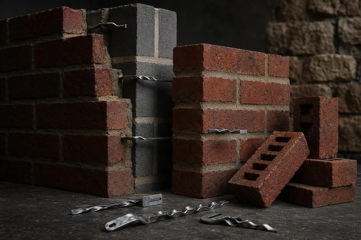
“Brick to brick wall ties” is not the name of one universal connector. The phrase can describe ties built into a new cavity wall, retrofit anchors connecting existing brick wythes, veneer anchors fixed to a masonry backup, or starters joining new brickwork to an existing wall.
Those applications impose different demands. Selection depends on the wall assembly, masonry condition, cavity or separation width, loads, exposure, movement, moisture detailing, installation method, and governing local requirements.
This article is therefore a non-prescriptive selection and terminology guide. It cannot establish a code-compliant layout or repair specification for a particular building. The available examples come mainly from commercial and manufacturer guidance across several jurisdictions; final design must rely on current local rules and the selected system’s approved documentation.
What “brick to brick wall ties” can mean
Begin by identifying what the two brick layers are and why they need to be connected.
A cavity wall has separate inner and outer leaves divided by a cavity. Depending on the design, that cavity may provide drainage, contain insulation, interrupt moisture transfer, or perform several functions. Ties restrain the leaves against separation without defeating the intended cavity or movement detail.
A solid multi-wythe wall also contains two or more layers of brick, but those wythes may be adjacent, separated by mortar, connected by headers, or restrained by older metalwork.
A masonry veneer over a masonry backup is another distinct assembly. The outer masonry is anchored to a supporting masonry wall. In general terms, masonry ties connect separate layers for stability, but their form and permitted movement depend on the complete wall design and applicable jurisdiction.
The principal project categories are:
- New two-leaf masonry: Both leaves are constructed together, allowing ties to be embedded in fresh mortar.
- Existing cavity-wall repair: Original ties are missing, insufficient, poorly installed, or deteriorated.
- Solid multi-wythe stabilization: Existing brick layers require restraint even though the wall is not a conventional drained cavity wall.
- Masonry veneer over a masonry backup: Anchors connect an outer veneer to supporting masonry.
- New-to-existing junction: A new wall meets existing masonry at a T-junction, corner, or in-line extension.
Establish the geometry—and whether the work is new or remedial—before selecting a product, length, or layout.
A useful first-pass decision tree is:
- Both leaves are new: Investigate a built-in masonry-to-masonry cavity tie.
- Both leaves already exist: Investigate a tested remedial mechanical, helical, resin, grout, or hybrid system.
- A new wall meets an existing wall: Investigate a wall-starter channel, frame cramp, screw-in starter tie, or properly designed toothed junction.
- The principal defect is a crack: Diagnose the cause before considering crack stitching.
- The masonry is substantially deteriorated or displaced: Assess the wall before attempting to select retrofit ties.
Wall ties and crack-stitching bars are not interchangeable. A wall tie connects one leaf, wythe, or façade to another. A stitching bar primarily transfers forces across a diagnosed crack. Simpson Strong-Tie’s manufacturer-authored overview illustrates these as separate applications with different installation concepts. See its comparison of helical wall ties and stitching ties.
Remedial ties can preserve suitable masonry without complete dismantling. They cannot, however, create a dependable connection where the receiving masonry cannot sustain the fixing. Manufacturer guidance on helical repairs likewise acknowledges that severely deteriorated brickwork may require demolition rather than tie repair.
Wall ties, helical ties, starters, anchors, and stitching bars compared
Product terminology varies by region and manufacturer. Terms such as “brick tie,” “wall tie,” “helical anchor,” and “stitch tie” may be used broadly, so the connector’s function and fixing mechanism are more informative than its marketing name.
A built-in cavity wall tie is laid into the mortar joints of both leaves as construction proceeds. It spans the cavity and is normally concealed when the wall is complete.
A remedial cavity tie is installed in an existing wall. Many systems require drilling through the outer leaf and into the inner leaf or backup. They may replace deteriorated original ties or add restraint where the existing tie arrangement is inadequate.
A helical wall tie is formed from a twisted metal profile, commonly stainless steel in façade-repair products. Its fins develop a frictional or mechanical connection as the tie is driven into a suitable receiving material. “Helical” describes the profile; it does not establish the tie’s capacity, compatible substrates, or required installation method.
Common remedial fixing technologies include:
- Mechanical expansion systems, which press against the receiving material when activated.
- Helical friction systems, which form a gripping path in the substrate.
- Resin systems, which bond a connector into a prepared hole.
- Cement-grouted systems, which use cementitious material to form the fixing.
- Hybrid systems, which use different fixing mechanisms at opposite ends.
For remedial work, assess three separate performance zones: the inner-leaf fixing, the section spanning the cavity or separation, and the outer-leaf fixing. This three-zone approach is explained in a specialist contractor’s discussion of remedial tie mechanisms, which also emphasizes that no single system is best for every substrate. Review the three-part remedial tie model.
A wall-starter channel is a vertical profile fixed to an existing wall. Ties engage with the channel and extend into the bed joints of the new work. A frame cramp is an individual connector fixed to the existing substrate and embedded in the new masonry. A screw-in starter tie is another proprietary junction connector.
A veneer anchor connects masonry veneer to a backup wall. Product categories may include complete anchoring systems alongside plates, rods, wire ties, reinforcement, and accessories. A listing on a masonry-to-masonry page does not prove that an item is a complete system for a particular double-brick wall. Heckmann’s product category, for example, includes several kinds of ties, anchors, plates, and reinforcement whose individual submittals must be examined. See the range of masonry-to-masonry components.
| Connector or system | Primary purpose | New or existing construction | Typical fixing method | Movement considerations | Visibility after installation | Evidence needed before specification |
|---|---|---|---|---|---|---|
| Built-in cavity tie | Restrain two new masonry leaves | New | Embedded in fresh bed joints | Must suit the wall’s intended differential-movement detail | Hidden | Current wall design, product declaration or certificate, resistance data, durability classification |
| Remedial mechanical tie | Reconnect existing leaves or a veneer and backup | Existing | Drilled fixing using expansion or another mechanical action | Must match the intended behavior of the wall | Head may require patching | Approved substrates, capacity, embedment, installation instructions, trial results |
| Helical wall tie | Provide retrofit restraint between wythes or between a façade and backup | Existing | Driven through a specified pilot hole | Any movement capability must be documented for the selected system | Often countersunk and patched | Substrate evidence, pilot-hole requirements, length, resistance and durability |
| Resin- or grout-fixed tie | Bond a connector into receiving material | Usually existing | Drilled, prepared, filled and set hole | A rigid connection may be unsuitable where sliding is required | Usually patchable | Material compatibility, hole preparation, hollow-unit detail, environmental and fire data |
| Wall-starter channel and ties | Connect new masonry at an existing-wall junction | New-to-existing | Channel fixed vertically; ties enter new bed joints | Sliding components may accommodate course alignment or specified movement | Mostly hidden | Junction design, channel-fixing data, substrate condition and movement detail |
| Frame cramp or screw-in starter tie | Restrain new masonry at a junction | New-to-existing | Individually fixed and embedded in a new bed joint | Depends on the approved connector and detail | Hidden after construction | Fixing resistance, spacing, geometry and installation instructions |
| Veneer anchor | Attach masonry veneer to masonry backup | New or remedial | Embedded, fastened or adjustable assembly | May need to accommodate controlled differential movement | Hidden | Complete-system documentation, compatible substrates, loads and durability |
| Crack-stitching bar | Transfer forces across a diagnosed crack | Existing repair | Installed in routed bed joints with repair mortar or grout | Reinforces a cracked zone rather than tying separate leaves by default | Concealed after repair | Crack diagnosis, layout, anchorage and compatible repair material |
A useful specification therefore identifies the intended function, complete system, substrate at each end, movement requirements, fixing method, and supporting evidence. A product name alone is insufficient.
How to select a tie for the actual wall
Selection starts with the assembly rather than a catalogue photograph. Record at least:
- Wall type: cavity wall, solid multi-wythe wall, veneer, or junction
- Actual cavity width or wythe separation
- Leaf thicknesses and available sound embedment
- Brick type and mortar condition in both leaves
- Wall height, openings, returns, parapets and unsupported edges
- Design loads and intended load path
- Relevant wind, seismic or other lateral demand
- Exposure and corrosion risk
- Required differential, thermal or longitudinal movement
- Drainage, insulation, membranes and damp-proofing
- Applicable regulations, standards, approvals and inspection requirements
Do not infer the remote substrate from the exposed brick. The inner leaf may be solid brick, perforated brick, hollow masonry, concrete masonry, stone, or another material. Even where both leaves are brick, their density, perforations, damage and mortar condition may differ.
For a remedial tie, assess the three zones separately.
1. Inner-leaf fixing: Determine whether the remote receiving material can develop the necessary resistance without splitting, crushing, or allowing the connector to pull out.
2. Cavity-spanning section: Confirm that the connector is suitable for the actual separation and intended load. It must also be compatible with the cavity’s drainage, insulation and membrane details.
3. Outer-leaf fixing: Establish whether enough sound material remains after drilling and whether installation can occur without unacceptable damage.
Mechanical expansion may form an effective fixing in suitable dense masonry, but the outward forces can be unreliable or damaging in soft, hollow, perforated, weak, or deteriorated units. Poorly filled joints and internal voids can also prevent consistent engagement.
Helical friction ties can suit some brick-to-brick repairs, but they remain substrate-dependent. Very hard units may resist proper driving, while soft or deteriorated units may not grip adequately. Voids, perforations, drilling damage, poor alignment, or insufficient effective embedment can reduce performance.
Resin and grout systems likewise depend on compatible, sufficiently sound material. The hole must be prepared as required by the selected system because dust and loose debris can prevent a dependable bond. Hollow units may require sleeves, mesh containment, grout socks, or another product-specific method. These limitations and fixing mechanisms are discussed in the specialist three-zone guidance cited above; they are not universal design rules.
Movement can be as important as resistance. Some junction and veneer details need to provide out-of-plane restraint while permitting specified longitudinal or differential movement. Whether a connector offers that behavior must be established from the approved wall detail and product evidence, not assumed from its shape.
Fire exposure, coastal or chemically aggressive conditions, high-wind or seismic demand, tall walls, parapets, and unusual geometry are project-specific design questions. The commercial sources used here do not establish a universal solution for those conditions. Similarly, “stainless steel” is not a complete durability specification: the required alloy or durability classification must be verified for the actual exposure.
There is consequently no useful universal ranking of the “best” brick-to-brick tie. Compare candidates by:
- Intended wall configuration
- Approved substrates
- Documented resistance in the relevant load modes
- Required sound embedment
- Permitted cavity or separation range
- Durability classification
- Documented movement characteristics
- Installation tolerances
- Approval or certification scope
- Inspection and verification provisions
A tie with a strong published result in dense concrete may not perform similarly in soft historic brick. Product performance and substrate compatibility must always be considered together.
Built-in ties for new brick cavity walls
When both leaves are new, masonry-to-masonry ties can be embedded in fresh bed joints as construction proceeds. This generally avoids retrofit drilling and allows the tie arrangement to be coordinated with coursing, openings, insulation and cavity drainage.
General installation principles reported by UK commercial guidance include:
- Use the specified tie type and length.
- Provide the approved embedment in each leaf.
- Bed ties in fresh mortar rather than pushing them into completed joints.
- Keep each tie aligned with the approved detail.
- Orient a formed drip downward near the cavity center.
- Provide the specified fall toward the outer leaf.
- Keep the cavity clear of significant mortar droppings.
- Coordinate insulation retainers without distorting the tie.
For certain UK cavity walls, Ancon reports a typical staggered layout of 900 mm horizontally by 450 mm vertically, equivalent to approximately 2.5 ties per square metre. The same manufacturer makes clear that tie choice depends on masonry type, cavity width, building height, geometry and exposure, so these figures are not a universal layout or a substitute for current project design. See Ancon’s UK-oriented wall-tie guidance.
Openings, unbonded edges, wider cavities, exposed sites, higher loads, or ties with limited design resistance may require additional connectors or a calculated layout. General field spacing should not simply continue through window, door, parapet, or edge zones without checking the applicable design.
Published embedment summaries also require context. BS Fixings reports at least 50 mm embedment into each leaf and says ties should be built into joints rather than pushed into them. The retailer also reports closer placement around unbonded openings, but its figures are UK-focused and attributed to a particular guidance environment. See the supplier’s embedment and placement summary.
Ancon separately reports 62–75 mm as typical mortar embedment at each end. The difference does not establish a choice between two universal values. Required embedment depends on the current governing rules, selected product, masonry, installation tolerance and wall design. The figures should be treated only as sourced UK examples.
Tie length must accommodate the actual cavity or separation and the required sound embedment in both leaves while remaining within the approved dimensions and tested scope of the product. Selecting solely from nominal cavity width can produce inadequate engagement or an unsuitable fit.
Stainless steel is commonly used for modern cavity ties, but material description alone does not demonstrate suitability. Confirm the specified grade or durability class for moisture, mortar, salts, coastal exposure, or other aggressive conditions.
Before construction, identify the governing jurisdiction and obtain the current wall design, applicable product declaration or certificate, resistance values, approved cavity range, durability designation and installation instructions. A retailer article or older manufacturer summary can explain terminology but cannot establish current compliance.
Remedial ties for existing double-brick and multi-wythe walls
Suitable existing walls may sometimes be re-anchored without dismantling the façade. Depending on the substrates and design, the repair may use mechanical expansion ties, driven helical ties, resin or grout fixings, or a hybrid system with different mechanisms at opposite leaves.
For a driven helical system, the high-level sequence commonly described by manufacturers is:
- Survey the wall and establish the required connection.
- Set out proposed fixing locations and check for known conflicts.
- Form the specified pilot hole through the outer brick and any gap into the receiving material.
- Drive the selected tie using its prescribed tool.
- Verify the installation under the project quality plan.
- Where the system permits, countersink and patch the head for a less conspicuous finish.
This sequence is not transferable to every remedial product. Pilot-hole diameter, drilling method, tool, embedment, fixing position and acceptance criteria are product-specific. The cited Simpson Strong-Tie overview describes drilling through existing brick and an air gap before driving a helical tie, but it does not provide a universal repair specification.
Some one-piece helical products are marketed as gripping masonry on both sides of a cavity. That may simplify installation, but capacity still depends on the exact product, brick type, cavity geometry, hole formation and effective engagement.
Important risks include:
- Concealed rear-face spalling during drilling
- Weak, cracked, soft, hollow or perforated units
- Insufficient sound embedment
- Voids along the fixing path
- Weak or missing mortar
- Misaligned or oversized pilot holes
- Inadequately prepared resin holes
- Conflicts with insulation, membranes or building services
- Local surface damage around the fixing head
Rear-face spalling is especially difficult to judge from the exterior. The specialist discussion of remedial tie selection specifically warns that drilling can damage the unseen rear face and reduce effective embedment. See the discussion of drilling damage and substrate testing.
Variable masonry may justify trial installations and project-defined tension or pull-out testing. Testing can indicate whether assumed substrate resistance is realistic, but the supplied evidence does not establish a universal method, sample rate, or acceptance value. Some through-driven systems may also be difficult to test without affecting the fixing. The designer must establish the verification plan for the selected system.
Remedial spacing must be derived from design demand, applicable requirements, documented product capacity, wall geometry, substrate results and appropriate design factors. New-build cavity-tie spacing, promotional retrofit densities and crack-stitching dimensions should not be transferred automatically.
Simpson Strong-Tie describes alternating helical-tie angles for one multi-wythe stabilization concept. That is a manufacturer-specific approach, not a general arrangement to copy without confirming the intended system, wall geometry, load path and supporting evidence.
Where permitted by the product, fixing heads can be countersunk and covered with a compatible repair material. The finishing method should follow the approved system and avoid concealing an installation before required inspection has occurred.
Claims about dramatic performance increases, exceptionally rapid installation, guaranteed composite action, large savings or decades of additional service life should not determine the specification. The relevant questions are narrower:
- Can the system form dependable fixings in both leaves?
- Is resistance documented for comparable substrates?
- Can installation be inspected or verified?
- Does the completed load path meet the project’s design demand?
Joining new brickwork to an existing wall
A new wall meeting existing masonry presents a junction problem, not automatically a cavity-tie replacement problem. The detail must address geometry, bond, restraint, movement and moisture.
Toothing
Traditional toothing involves removing alternate existing bricks so that new masonry can interlock with the resulting teeth. It can continue the visible bond, especially at an in-line extension, but it also disturbs the existing wall.
The masonry must be suitable for controlled removal, and the resulting junction must provide the required bond and restraint.
Channel-and-tie wall starters
A wall-starter system uses a vertical channel fixed to the existing wall. Ties engage with the channel and are embedded in the bed joints of the new masonry.
Some systems use preset integral ties, which can simplify layout where the system and new coursing align. Others use sliding ties, which can be positioned to match new bed joints and may provide additional flexibility where course levels vary.
Ancon’s manufacturer guide describes toothing, starter channels and screw-in starter ties. It also publishes dimensions and installation details for particular products, but those values belong only to the named systems and cannot be generalized. See Ancon’s overview of new-to-existing wall junctions.
Frame cramps and screw-in starter ties
Frame cramps are individually fixed to the existing wall and embedded in the new work. Proprietary screw-in starter ties perform a similar junction function.
Their spacing, angle, embedment, fastener and substrate requirements must come from the selected system’s approved detail. Individual connectors may be useful where a continuous channel is impractical, but they require accurate setting-out and dependable individual fixings. A channel may simplify alignment, yet its fasteners still need suitable resistance in the existing masonry.
T-junctions and in-line extensions
At a T-junction, the new wall meets the face of the existing wall. A starter channel or individual cramps may provide restraint while the junction is detailed for the required movement and moisture control.
At an in-line extension, new work continues from an existing end or corner. Toothing may continue the visible outer bond, while the inner leaf may use starters or other connectors. Visual continuity and structural restraint are separate issues: an apparently continuous brick bond does not by itself prove an adequate load path.
For a new cavity wall, connecting the new wall to the existing building does not eliminate the need to connect the new inner and outer leaves where the cavity-wall design requires ties. Junction connectors and cavity ties perform different functions.
The final junction detail may need to address:
- Cavity continuity or closure
- Drainage and weeps
- Insulation continuity
- A vertical damp-proofing detail
- Cold-bridge reduction
- Flashings or cavity trays
- Differential and longitudinal movement
- Restraint of both leaves
- Compatibility with the wall and foundation movement
These considerations do not establish one universal junction detail. The project designer and relevant approval or inspection authority should confirm the arrangement under current local requirements.
Survey, installation, and quality-assurance workflow
A structured investigation is more reliable than choosing a connector from an exterior photograph.
Before installation
Classify the assembly. Determine whether it is a cavity wall, solid multi-wythe wall, veneer over backup, or a new-to-existing junction. Record leaf thicknesses, cavity width and the likely receiving materials.
Inspect the masonry. Note brick type, known perforations, mortar condition, cracking, bulging, displacement, loose units, weathering and previous repairs. Examine both sides where accessible.
Investigate moisture and movement. Look for water-entry paths, defective drainage details, movement joints, settlement indicators and repeated cracking.
Establish design requirements. Confirm wall height, exposure, openings, edges, parapets, design loads, required movement and the governing jurisdiction.
Check for concealed components. Before drilling, use the project’s approved procedure to assess the likely locations of services, insulation, membranes, cavity trays and flashings. This article does not provide a concealed-hazard detection method.
Review the complete product documentation. Obtain the current declaration, specification, certificate or approval relevant to the jurisdiction, together with substrate data, dimensions, capacities, durability designation, installation instructions and finishing method.
Undertake trials where required. In variable existing masonry, trial fixings and project-defined verification testing may be necessary before committing to the full layout. A failed trial should prompt reassessment of the substrate, hole formation, connector, embedment or overall repair strategy.
During installation
Project records may include:
- Product and tie type
- Batch or traceability information
- Tie locations
- Pilot-hole dimensions where applicable
- Drilling observations
- Observed voids or deterioration
- Intended and achieved embedment
- Failed or abandoned holes
- Verification-test locations and results
- Repairs to the visible surface
For resin fixings, hole preparation must follow the selected system’s documented procedure. Dust and loose material can isolate the bonding material from the substrate. A clean-looking exterior hole does not rule out concealed rear-face damage, internal voids or perforations.
For new cavity-wall work, inspection should check:
- Correct tie type and length
- Embedment in fresh mortar
- Required tie fall and drip orientation
- Approved field layout
- Additional placement at openings and edges
- Cavity cleanliness
- Coordination with insulation
- Specified durability classification
After installation
Where permitted, patch fixing holes using the documented finishing method and a material selected for compatibility with the existing masonry. Do not cover work before required inspections or verification have been completed.
Retain drawings, marked tie locations, product records, test results, photographs, nonconformance records and repair details. These records support project acceptance and future inspection.
This workflow is a selection and detailing reference. It is not an installation manual, a repair design, or a substitute for structural assessment.
Failure signs and when tying is not enough
Wall ties may become ineffective because too few were installed, installation was poor, the original detail was unsuitable, or older steel ties deteriorated.
Manufacturer guidance reports that corroding steel strip ties can expand within bed joints and contribute to horizontal cracking. Deteriorated wire ties may lose section or cease to restrain the outer leaf, increasing its vulnerability to lateral loading. See Thor Helical’s description of strip- and wire-tie deterioration.
Warning signs that warrant specialist investigation include:
- Horizontal cracking along mortar bed joints
- Bulging or bowing
- Visible displacement
- Loose or rocking masonry
- Separation between wythes
- Rust-related cracking or staining
- Water penetration associated with the wall detail
- Repeated cracking after repair
- Failed trial fixings
- Falling masonry or local loss of material
These signs do not prove wall-tie failure. The cause must be diagnosed before a remedial layout is chosen.
Remedial ties may be appropriate where sound areas of masonry can form reliable fixings and the completed system provides a designed load path. The work may form part of a broader repair involving repointing, local unit replacement, moisture correction, or treatment of deteriorated original ties.
Simpson Strong-Tie’s manufacturer guidance notes that badly deteriorated brickwork may require demolition rather than helical repair; any immediate concern about collapse or falling masonry requires prompt site-specific professional action. Review the manufacturer’s stated repair limitation.
Professional structural or masonry review is particularly important where there is:
- Significant bulging or displacement
- An uncertain load path
- A tall, highly exposed or unusually shaped wall
- A parapet or free-standing element
- Weak, hollow or highly variable masonry
- Repeated failed trial fixings
- Extensive cracking
- Significant wind or seismic demand
- Evidence of support failure
- An immediate risk from loose or falling masonry
The correct decision sequence is more important than any product recommendation: identify the wall assembly and required connection; distinguish new construction from repair; assess both leaves and the cavity or junction; select a fixing mechanism supported by relevant product and substrate evidence; and verify length, layout, durability, movement, moisture and installation against current local requirements.
Remedial ties can preserve suitable masonry. Visible instability, severe deterioration, extensive cracking or failed trials should shift the priority from purchasing ties to professional assessment and an appropriate stabilization or reconstruction strategy.
Frequently asked questions
What spacing should be used for brick-to-brick wall ties?
There is no universal spacing for every brick-to-brick application.
For certain new UK cavity walls, Ancon reports a typical staggered pattern of 900 mm horizontally by 450 mm vertically, or approximately 2.5 ties per square metre. These are contextual commercial-guidance figures, not a specification for every wall. Openings, edges, wider cavities, exposed sites, unusual geometry, higher loads or limited tie resistance may require additional ties or a calculated layout. See the source and its selection qualifications.
For remedial walls, derive the layout from design demand, documented connector resistance, substrate condition, geometry, applicable rules and the project’s design factors. Do not automatically apply new-build or crack-stitching spacing.
How long should a brick-to-brick wall tie be?
The tie must span the actual cavity or separation and achieve the required sound embedment in both leaves while remaining within the selected product’s approved dimensions and tested limits.
Do not select length from cavity width alone. UK commercial summaries differ: BS Fixings reports at least 50 mm embedment into each leaf, while Ancon reports 62–75 mm as typical embedment at each end. Those figures belong to their stated UK context and do not replace current governing requirements or product documentation. See the 50 mm supplier summary.
Suspected rear-face damage is not simply an allowance to add to tie length. It requires assessment of whether sound effective embedment can be achieved, potentially through trials, verification or a revised fixing strategy.
Can failed cavity wall ties be replaced without removing the brick façade?
Often they can, provided both leaves contain suitable material for reliable fixings. Mechanical, helical, resin, grout or hybrid ties may be installed through the outer leaf to reconnect existing masonry.
Suitability depends on wall condition, cavity geometry, required resistance, access, substrate compatibility and trial results. PROSOCO describes helical retrofit anchors used to reattach existing masonry to backup structures, but its article is manufacturer promotional guidance rather than proof of suitability for an individual wall. See the described retrofit application.
A severely deteriorated, substantially displaced or unstable façade may require a different repair strategy.
Is a helical wall tie the same as a crack-stitching tie?
No. Both may use twisted metal profiles, but their primary functions differ.
A helical wall tie connects a masonry leaf or wythe to another wythe or backup. A crack-stitching bar is installed across a diagnosed crack to transfer forces through the cracked zone. Product dimensions, orientation, anchorage and layout can therefore differ.
Do not use crack-stitching dimensions as cavity-wall tie spacing unless a project-specific design expressly combines those functions.
What signs can indicate missing, corroded, or ineffective wall ties?
Thor Helical specifically associates expanding strip-tie corrosion with horizontal bed-joint cracking and deteriorated wire ties with loss of façade restraint. See the manufacturer’s failure description.
These signs are not conclusive. They can overlap with support movement, thermal effects, defective drainage, lintel problems and corrosion of other embedded metalwork. Diagnosis should precede selection of a remedial system.